Return to Section TOC
Return to Section TOC
Return to Master TOC
Return to Master TOC
TROUBLESHOOTING & REPAIR
ENGINE THROTTLE ADJUSTMENT TEST (continued)
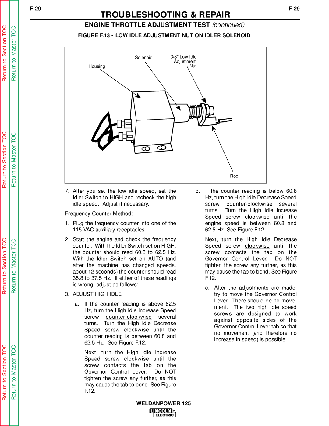
FIGURE F.13 - LOW IDLE ADJUSTMENT NUT ON IDLER SOLENOID
|
|
|
|
|
|
|
|
|
|
|
|
|
|
|
|
|
|
|
| Solenoid | 3/8" Low Idle |
|
|
|
|
|
|
|
|
|
|
|
|
|
|
|
|
|
|
|
|
| Adjustment |
Housing | Nut | ||||||||||||||||||||
|
|
|
|
|
|
|
|
|
|
|
|
|
|
|
|
|
|
|
|
|
|
|
|
|
|
|
|
|
|
|
|
|
|
|
|
|
|
|
|
|
|
|
|
Rod
Return to Section TOC
Return to Section TOC
Return to Master TOC
Return to Master TOC
7.After you set the low idle speed, set the Idler Switch to HIGH and recheck the high idle speed. Adjust if necessary.
Frequency Counter Method:
1.Plug the frequency counter into one of the 115 VAC auxiliary receptacles.
2.Start the engine and check the frequency counter. With the Idler Switch set on HIGH, the counter should read 60.8 to 62.5 Hz. With the Idler Switch set on AUTO (and after the machine has changed speeds, about 12 seconds) the counter should read 35.8 to 37.5 Hz. If either of these readings is wrong, adjust as follows:
3.ADJUST HIGH IDLE:
a.If the counter reading is above 62.5 Hz, turn the High Idle Increase Speed screw
Next, turn the High Idle Increase Speed screw clockwise until the screw contacts the tab on the Governor Control Lever. Do NOT tighten the screw any further, as this may cause the tab to bend. See Figure F.12.
b.If the counter reading is below 60.8 Hz, turn the High Idle Decrease Speed screw
Next, turn the High Idle Decrease Speed screw clockwise until the screw contacts the tab on the Governor Control Lever. Do NOT tighten the screw any further, as this may cause the tab to bend. See Figure F.12.
c.After the adjustments are made, try to move the Governor Control Lever. There should be no move- ment. The two high idle speed screws are designed to work against opposite sides of the Governor Control Lever tab so that no movement (and therefore no increase in speed) is possible.
WELDANPOWER 125