Marathon Monitors Inc.
| Name | Description |
|
|
|
|
|
|
|
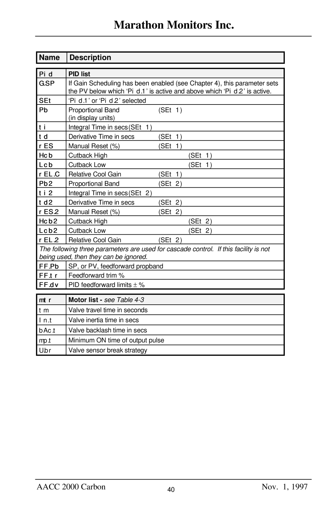
| Pid | PID list |
|
|
| G.SP | If Gain Scheduling has been enabled (see Chapter 4), this parameter sets |
| |
|
| the PV below which ‘Pid.1’ is active and above which ‘Pid.2’ is active. |
| |
| SEt | ‘Pid.1’ or ‘Pid.2’ selected |
|
|
| Pb | Proportional Band | (SEt 1) |
|
|
| (in display units) |
|
|
| ti | Integral Time in secs(SEt 1) |
|
|
| td | Derivative Time in secs | (SEt 1) |
|
| rES | Manual Reset (%) | (SEt 1) |
|
| Hcb | Cutback High | (SEt 1) |
|
| Lcb | Cutback Low | (SEt 1) |
|
| rEL.C | Relative Cool Gain | (SEt 1) |
|
| Pb2 | Proportional Band | (SEt 2) |
|
| ti2 | Integral Time in secs(SEt 2) |
|
|
| td2 | Derivative Time in secs | (SEt 2) |
|
| rES.2 | Manual Reset (%) | (SEt 2) |
|
| Hcb2 | Cutback High | (SEt 2) |
|
| Lcb2 | Cutback Low | (SEt 2) |
|
| rEL.2 | Relative Cool Gain | (SEt 2) |
|
The following three parameters are used for cascade control. If this facility is not being used, then they can be ignored.
FF.Pb | SP, or PV, feedforward propband |
FF.tr | Feedforward trim % |
FF.dv | PID feedforward limits ± % |
|
|
mtr | Motor list - see Table |
tm | Valve travel time in seconds |
In.t | Valve inertia time in secs |
bAc.t | Valve backlash time in secs |
mp.t | Minimum ON time of output pulse |
U.br | Valve sensor break strategy |
AACC 2000 Carbon | 40 | Nov. 1, 1997 |
|
|