Marathon Monitors Inc.
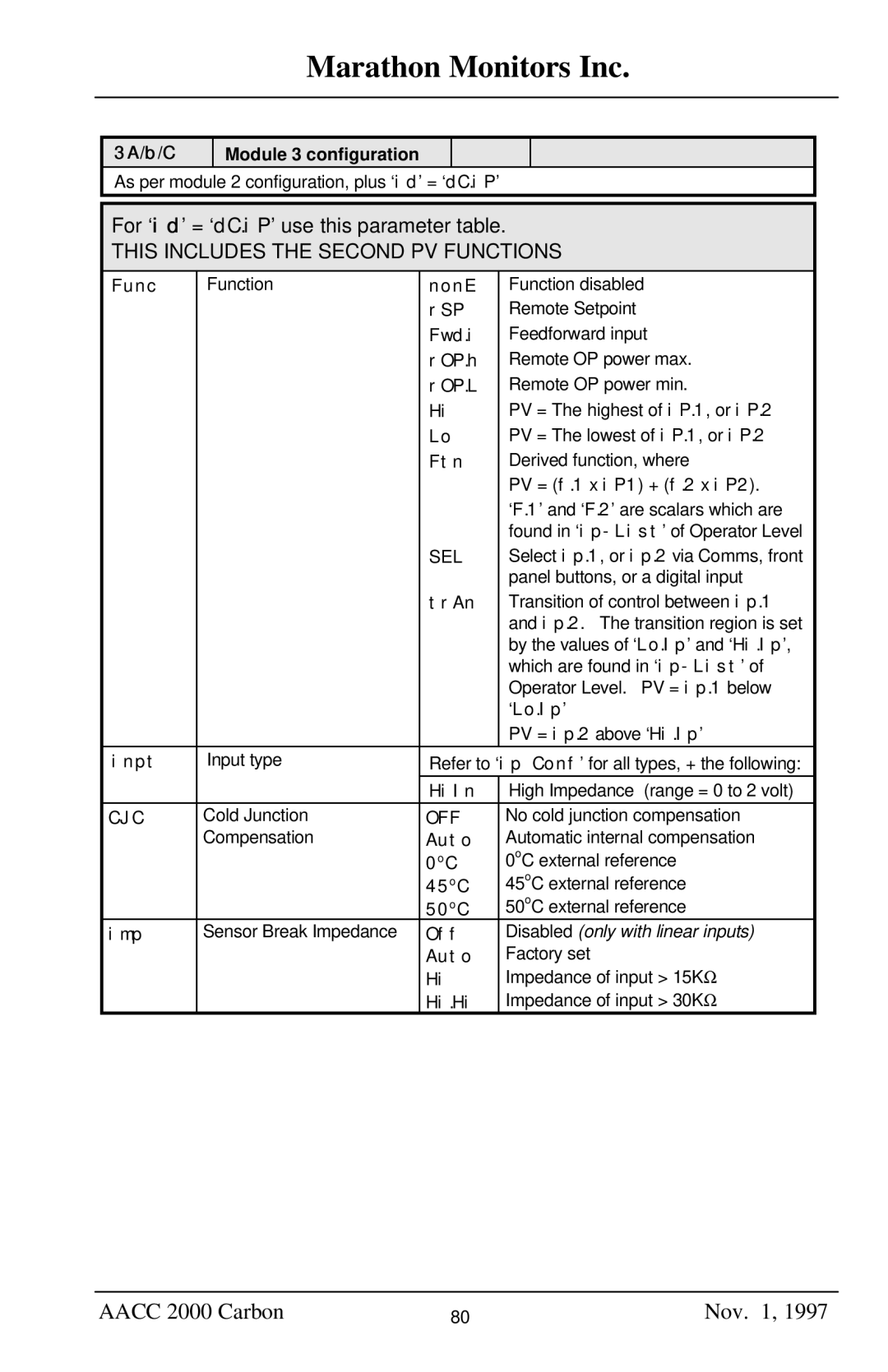
3A/b/C
Module 3 configuration
As per module 2 configuration, plus ‘id’ = ‘dC.iP’
For ‘id’ = ‘dC.iP’ use this parameter table.
THIS INCLUDES THE SECOND PV FUNCTIONS
Func | Function | nonE |
| Function disabled | |
|
| rSP |
| Remote Setpoint | |
|
| Fwd.i |
| Feedforward input | |
|
| rOP.h |
| Remote OP power max. | |
|
| rOP.L |
| Remote OP power min. | |
|
| Hi |
| PV = The highest of iP.1, or iP.2 | |
|
| Lo |
| PV = The lowest of iP.1, or iP.2 | |
|
| Ftn |
| Derived function, where | |
|
|
|
| PV = (f.1 x iP1) + (f.2 x iP2). | |
|
|
|
| ‘F.1’ and ‘F.2’ are scalars which are | |
|
|
|
| found in | |
|
| SEL |
| Select ip.1, or ip.2 via Comms, front | |
|
|
|
| panel buttons, or a digital input | |
|
| trAn |
| Transition of control between ip.1 | |
|
|
|
| and ip.2. The transition region is set | |
|
|
|
| by the values of ‘Lo.Ip’ and ‘Hi.Ip’, | |
|
|
|
| which are found in | |
|
|
|
| Operator Level. PV = ip.1 below | |
|
|
|
| ‘Lo.Ip’ |
|
|
|
|
| PV = ip.2 above ‘Hi.Ip’ | |
inpt | Input type |
| ip Conf | ’ for all types, + the following: | |
|
| Refer to ‘ |
| ||
|
| HiIn |
| High Impedance (range = 0 to 2 volt) | |
CJC | Cold Junction | OFF |
| No cold junction compensation | |
| Compensation | Auto |
| Automatic internal compensation | |
|
| 0oC |
| 0oC external reference | |
|
| 45oC |
| 45oC external reference | |
|
| 50oC |
| 50oC external reference | |
imp | Sensor Break Impedance | Off |
| Disabled (only with linear inputs) | |
|
| Auto |
| Factory set | |
|
| Hi |
| Impedance of input > 15KΩ | |
|
| Hi.Hi | Impedance of input > 30KΩ | ||
AACC 2000 Carbon | 80 | Nov. 1, 1997 |