Marathon Monitors Inc.

All electrical connections are made to the screw terminals at the rear of the controller. If you wish to use crimp connectors, the correct size is AMP part number 349262-1. They accept wire sizes from 0.5 to 1.5 mm2 (16 to 22 AWG). A set of connectors is supplied with the controller. The terminals are protected by a clear plastic hinged cover to prevent hands, or metal, making accidental contact with live wires.

Rear terminal layouts

The rear terminal layouts are shown in Figure 1-6. The right-hand column carries the connections to the power supply, digital inputs 1 and 2, alarm relay and sensor input. The second and third columns from the right carry the connections to the plug-in modules. The connections depend upon the type of module installed, if any. To determine which plug-in modules are fitted, refer to the ordering code and wiring data on the controller side labels.

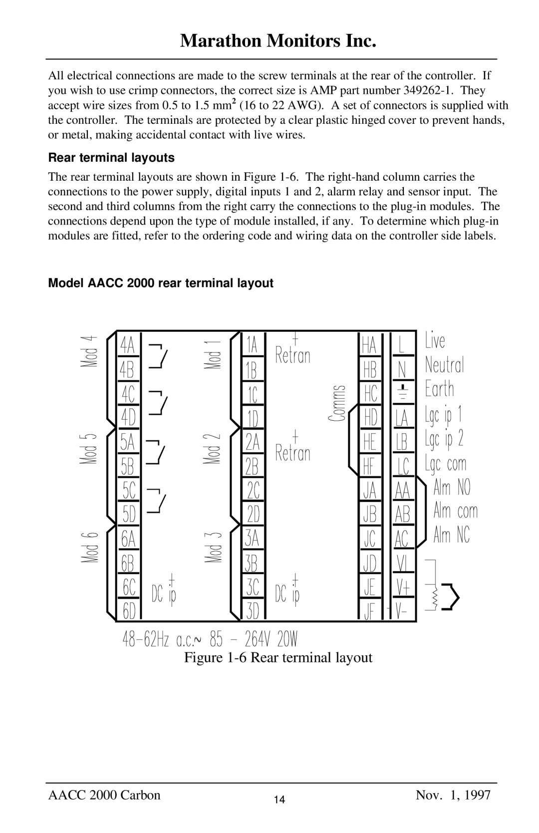
Model AACC 2000 rear terminal layout

Figure 1-6 Rear terminal layout

AACC 2000 Carbon

14

Nov. 1, 1997


Page 14
Image 14
Marathon Computer AACC 2000 manual Rear terminal layouts, Model Aacc 2000 rear terminal layout