Disassembly (Fig. 60)
![]() WARNING
WARNING
If the wheel motor is not held firmly in the vise, it could dislodge during service and cause in- jury.
1.Place wheel motor in a soft jawed vice with the cou- pling shaft (11) pointed down and the vise jaws clamping firmly on the sides of the housing (3).
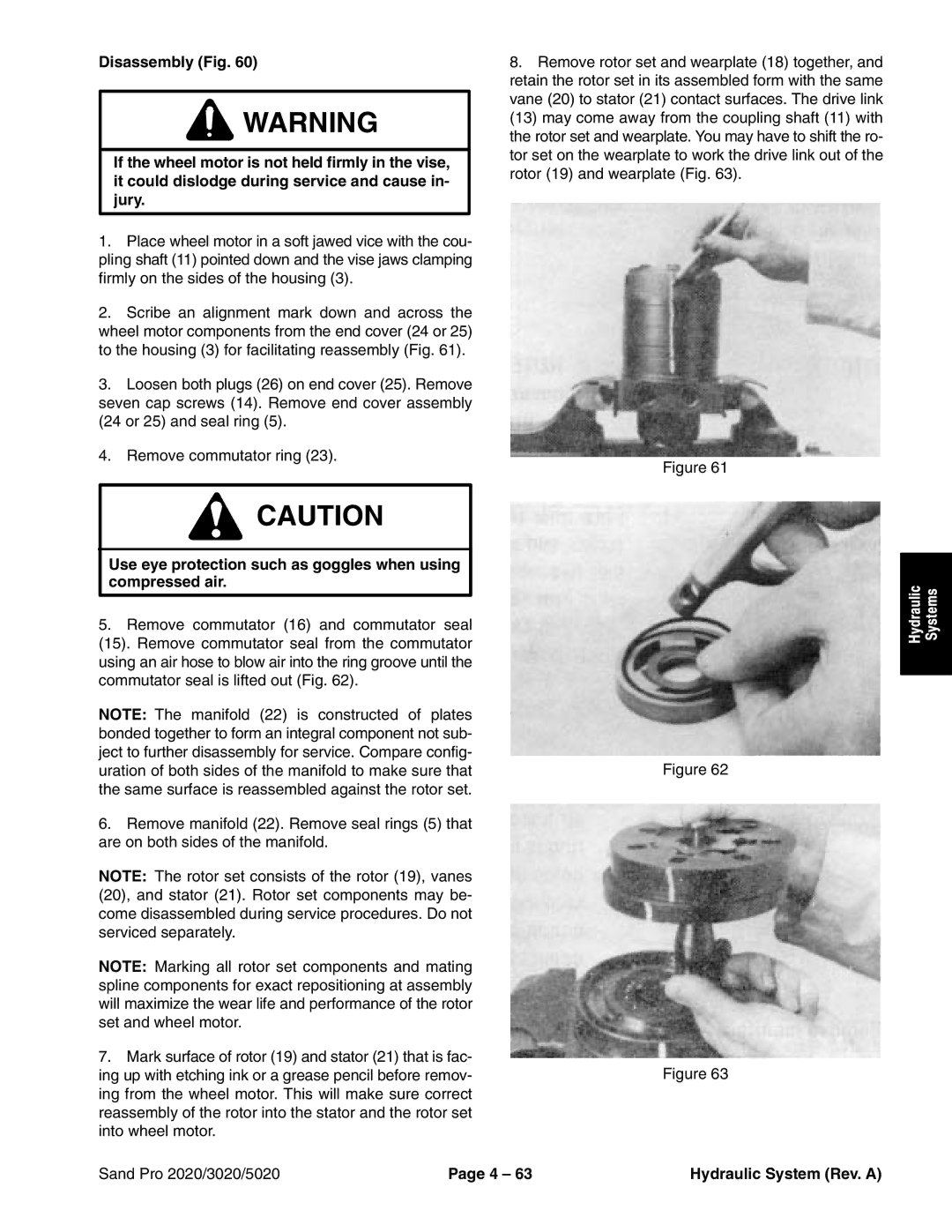
2.Scribe an alignment mark down and across the wheel motor components from the end cover (24 or 25) to the housing (3) for facilitating reassembly (Fig. 61).
3.Loosen both plugs (26) on end cover (25). Remove seven cap screws (14). Remove end cover assembly (24 or 25) and seal ring (5).
4.Remove commutator ring (23).
![]() CAUTION
CAUTION
Use eye protection such as goggles when using compressed air.
5.Remove commutator (16) and commutator seal
(15). Remove commutator seal from the commutator using an air hose to blow air into the ring groove until the commutator seal is lifted out (Fig. 62).
NOTE: The manifold (22) is constructed of plates bonded together to form an integral component not sub- ject to further disassembly for service. Compare config- uration of both sides of the manifold to make sure that the same surface is reassembled against the rotor set.
6.Remove manifold (22). Remove seal rings (5) that are on both sides of the manifold.
NOTE: The rotor set consists of the rotor (19), vanes (20), and stator (21). Rotor set components may be- come disassembled during service procedures. Do not serviced separately.
NOTE: Marking all rotor set components and mating spline components for exact repositioning at assembly will maximize the wear life and performance of the rotor set and wheel motor.
7.Mark surface of rotor (19) and stator (21) that is fac- ing up with etching ink or a grease pencil before remov- ing from the wheel motor. This will make sure correct reassembly of the rotor into the stator and the rotor set into wheel motor.
8.Remove rotor set and wearplate (18) together, and retain the rotor set in its assembled form with the same vane (20) to stator (21) contact surfaces. The drive link (13) may come away from the coupling shaft (11) with the rotor set and wearplate. You may have to shift the ro- tor set on the wearplate to work the drive link out of the rotor (19) and wearplate (Fig. 63).
Figure 61
Hydraulic | Systems |
|
|
Figure 62
Figure 63
Sand Pro 2020/3020/5020 | Page 4 – 63 | Hydraulic System (Rev. A) |