9.Remove seal ring (5) that is between the rotor set and wearplate (18).
10.Remove drive link (13) from the coupling shaft (11) if it was not removed with rotor set and wear plate (18). Remove seal ring (5) from housing (3).
11.Remove thrust bearing (12) from the top of the cou- pling shaft (11).
12.Check exposed portion of coupling shaft (11). Re- moved all signs of rust and corrosion which might pre- vent its withdrawal of shaft through the dirt and water seal (1) and outer bearing (2). Crocus cloth or fine emery paper may be used.
13.Remove coupling shaft (11) from the housing (3); push on the output end of the shaft.
14.Remove inner seal (7) and
15.Remove housing (3) from the vise and invert it. Re- move dirt and water seal (1). A blind hole bearing or seal puller is required.
IMPORTANT: NOTE position of the springs (28), shuttle valve (29), and ball (30) as they are removed from end cover (24).
16.Match mark one plug (26) and end cover (24). Re- move that plug and
Inspection (Fig. 60)
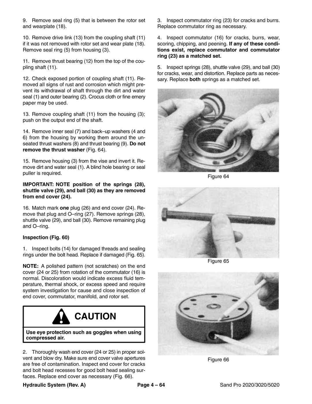
1.Inspect bolts (14) for damaged threads and sealing rings under the bolt head. Replace if damaged (Fig. 65).
NOTE: A polished pattern (not scratches) on the end cover (24 or 25) from rotation of the commutator (16) is normal. Discoloration would indicate excess fluid tem- perature, thermal shock, or excess speed and require system investigation for cause and close inspection of end cover, commutator, manifold, and rotor set.
![]() CAUTION
CAUTION
Use eye protection such as goggles when using compressed air.
2.Thoroughly wash end cover (24 or 25) in proper sol- vent and blow dry. Make sure end cover valve apertures are free of contamination. Inspect end cover for cracks and bolt head recesses for good bolt head sealing sur- faces. Replace end cover as necessary (Fig. 66).
3.Inspect commutator ring (23) for cracks and burrs. Replace commutator ring as necessary.
4.Inspect commutator (16) for cracks, burrs, wear, scoring, chipping, and peening. If any of these condi- tions exist, replace commutator and commutator ring (23) as a matched set.
5.Inspect springs (28), shuttle valve (29), and ball (30) for cracks, wear, and distortion. Replace parts as neces- sary. Replace both springs as a matched set.
Figure 64
Figure 65
Figure 66
Hydraulic System (Rev. A) | Page 4 – 64 | Sand Pro 2020/3020/5020 |