6.Apply masking tape around splines or keyway on coupling shaft (11) to prevent damage to seal.
IMPORTANT: The outer bearing (2) is not lubricated by the system’s hydraulic fluid. Make sure it is thor- oughly packed with Mobil Mobilith SHC R 460 grease.
NOTE: Coupling shaft (11) should be approximately
0.10inch (2.54 mm) below the housing wear plate sur- face to allow the assembly of the thrust bearing (12). The coupling shaft must rotate smoothly on the thrust bear- ing (9) and thrust washer (8) (Fig. 76).
7.Make sure that a generous amount of clean corro- sion resistant grease has been applied to the outer bear- ing (2). Install the coupling shaft (11) into housing (3), and seat shaft against the second thrust washer (8).
8.Install thrust bearing (12) onto the end of coupling shaft (11).
9.Apply a small amount of clean petroleum jelly to a new seal ring (5) and insert it into the housing (3) seal ring groove.
NOTE: One or two alignment studs screwed finger tight into housing (3) bolt holes, approximately 180 degrees apart, will facilitate the assembly and alignment of com- ponents as required in the following procedures. The studs can be made by cutting off the heads of
NOTE: Use any alignment marks put on the coupling shaft (11) and drive link (13) before disassembly to as- semble the drive link splines in their original position in the mating coupling shaft splines.
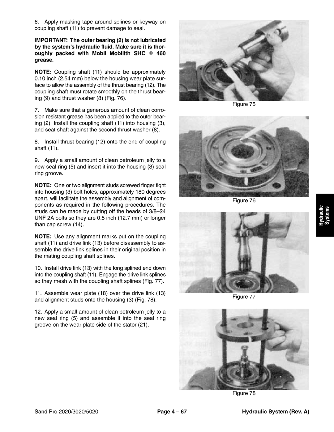
10.Install drive link (13) with the long splined end down into the coupling shaft (11). Engage the drive link splines so they mesh with the coupling shaft splines (Fig. 77).
11.Assemble wear plate (18) over the drive link (13) and alignment studs onto the housing (3) (Fig. 78).
12.Apply a small amount of clean petroleum jelly to a new seal ring (5) and assemble it into the seal ring groove on the wear plate side of the stator (21).
Figure 75
Figure 76
Figure 77
Figure 78
Hydraulic | Systems |
|
|
Sand Pro 2020/3020/5020 | Page 4 – 67 | Hydraulic System (Rev. A) |