Fuel Tank Removal (Fig. 32)
1.Park machine on a level surface, lower attachment, stop the engine, engage parking brake, and remove the key from the ignition switch.
2.Pivot seat up. Remove litter box (26) from the frame.
3.Disconnect and remove battery from the machine to prevent possible spillage of fuel on the battery (see Bat- tery Service in Chapter 5 – Electrical Systems).
![]() DANGER
DANGER
Gasoline is flammable. Use caution when storing or handling it. Do not drain fuel tank while the en- gine is running, or when the machine is in an en- closed area. Vapors may build up and be ignited by a spark or flame source many feet away. DO NOT SMOKE while draining the fuel tank to pre- vent the possibility of an explosion. Always drain fuel tank outside. Wipe up any spilled gasoline. Store gasoline in a clean,
4.Drain fuel tank (2) as follows:
A.Close fuel shutoff valve (24).
B.Disconnect fuel hose (22) from the fuel filter (31). Use funnel and hose to drain the fuel into a suitable container for storage.
C.Drain fuel tank completely by opening the fuel shutoff valve. Close fuel shutoff valve when tank is drained.
5.Loosen hose clamp (7) and disconnect fuel hose (8) from the bottom of the fuel tank (2).
6.Remove four philips pan head screws (6) and flat washers (28) securing the fuel tank (2) to the fuel tank base (4).
7.Lift fuel tank (2) from fuel tank base (4). Make sure not to lose grommets (3).
8.If the fuel tank base (4) is to be removed,
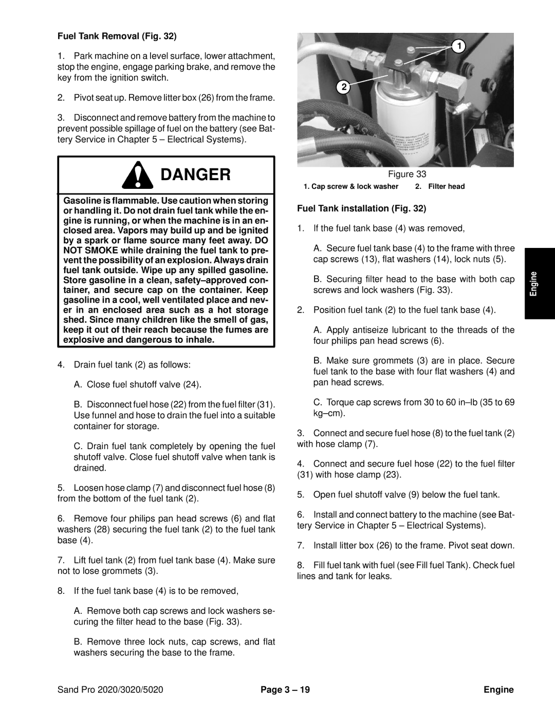
A.Remove both cap screws and lock washers se- curing the filter head to the base (Fig. 33).
B.Remove three lock nuts, cap screws, and flat washers securing the base to the frame.
1
2
Figure 33
1. Cap screw & lock washer | 2. Filter head |
| |
Fuel Tank installation (Fig. 32) |
| ||
1. | If the fuel tank base (4) was removed, |
| |
| A. Secure fuel tank base (4) to the frame with three |
| |
|
| ||
| cap screws (13), flat washers (14), lock nuts (5). | Engine | |
| screws and lock washers (Fig. 33). | ||
| B. Securing filter head to the base with both cap |
| |
2. | Position fuel tank (2) to the fuel tank base (4). |
| |
|
|
| |
| A. Apply antiseize lubricant to the threads of the |
| |
| four philips pan head screws (6). |
| |
| B. Make sure grommets (3) are in place. Secure |
| |
| fuel tank to the base with four flat washers (4) and |
| |
| pan head screws. |
|
|
| C. Torque cap screws from 30 to 60 |
| |
|
|
| |
3. | Connect and secure fuel hose (8) to the fuel tank (2) |
| |
with hose clamp (7). |
|
| |
4. | Connect and secure fuel hose (22) to the fuel filter |
| |
(31) with hose clamp (23). |
|
| |
5. | Open fuel shutoff valve (9) below the fuel tank. |
| |
6. | Install and connect battery to the machine (see Bat- |
| |
tery Service in Chapter 5 – Electrical Systems). |
| ||
7. | Install litter box (26) to the frame. Pivot seat down. |
| |
8. | Fill fuel tank with fuel (see Fill fuel Tank). Check fuel |
| |
lines and tank for leaks.
Sand Pro 2020/3020/5020 | Page 3 – 19 | Engine |