3.Reinstall
4.Install woodruff key (9) and fan hub (27) with cooling fan (28) to the hydrostat shaft. Secure hub to shaft with both set screws.
5.Secure hydrostat (8) to engine base with both sock- et head screws (20) and lock nuts (10).
6.Reinstall engine and hydrostat as follows:
![]() CAUTION
CAUTION
One person should operate the chain fall or jack while the other person guides the engine to the frame.
IMPORTANT: When repositioning the engine and hydrostat to the frame, make sure not the damage the cooling fan, wires, hoses, and cables.
14.Install left fender and seat (see Left Fender (Seat Base) Installation in Chapter 6 – Wheels, Brakes, and Miscellaneous). Install left and right side panels to the machine. Lower seat.
15.Charge hydraulic system (see Charge Hydraulic System).
2
1
Figure 37
1. | 2. Fuel hose |
A.Use jack or chain fall to position the front engine mounts and engine support to the frame (Fig. 38 and 39).
B.Secure engine mount to the frame with four cap screws and flat washers (Fig. 39).
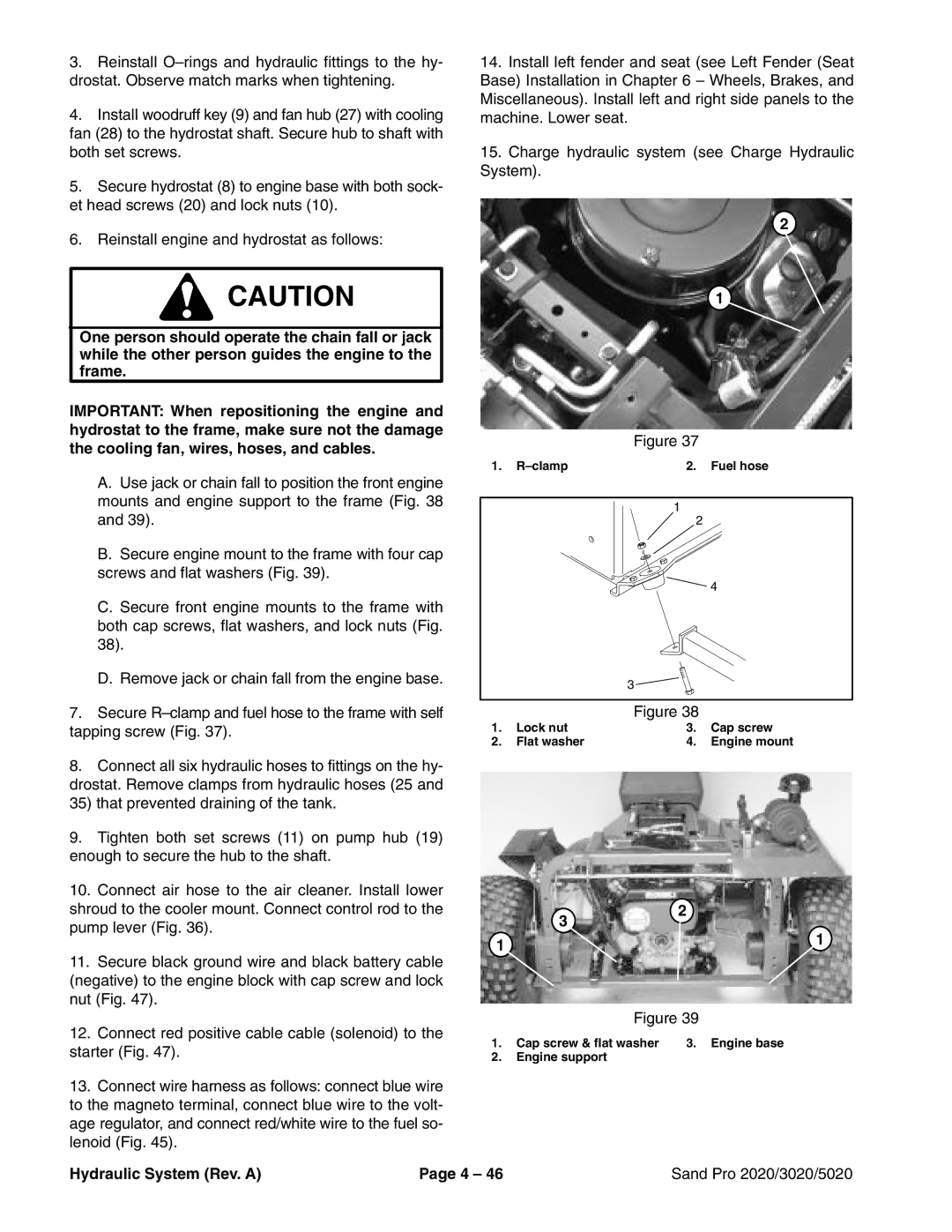
C.Secure front engine mounts to the frame with both cap screws, flat washers, and lock nuts (Fig. 38).
D.Remove jack or chain fall from the engine base.
7.Secure
8.Connect all six hydraulic hoses to fittings on the hy- drostat. Remove clamps from hydraulic hoses (25 and 35) that prevented draining of the tank.
9.Tighten both set screws (11) on pump hub (19) enough to secure the hub to the shaft.
10.Connect air hose to the air cleaner. Install lower shroud to the cooler mount. Connect control rod to the pump lever (Fig. 36).
11.Secure black ground wire and black battery cable (negative) to the engine block with cap screw and lock nut (Fig. 47).
12.Connect red positive cable cable (solenoid) to the starter (Fig. 47).
13.Connect wire harness as follows: connect blue wire to the magneto terminal, connect blue wire to the volt- age regulator, and connect red/white wire to the fuel so- lenoid (Fig. 45).
1
2
![]() 4
4
3 ![]()
Figure 38
1. | Lock nut | 3. | Cap screw |
2. | Flat washer | 4. | Engine mount |
3 | 2 | |
1 | ||
1 | ||
| ||
Figure 39 | ||
1. Cap screw & flat washer | 3. Engine base | |
2.Engine support
Hydraulic System (Rev. A) | Page 4 – 46 | Sand Pro 2020/3020/5020 |