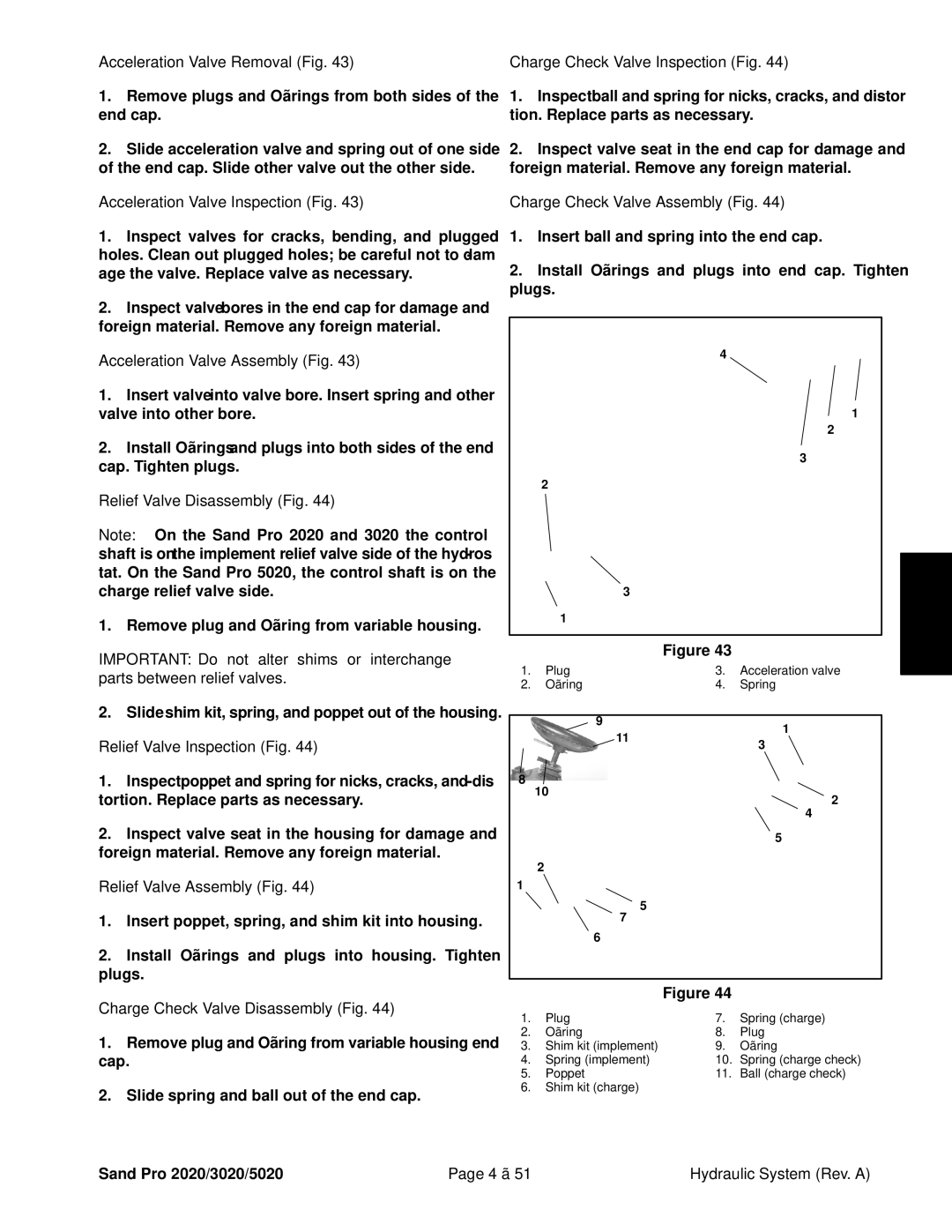
Acceleration Valve Removal (Fig. 43)
1.Remove plugs and
2.Slide acceleration valve and spring out of one side of the end cap. Slide other valve out the other side.
Acceleration Valve Inspection (Fig. 43)
1.Inspect valves for cracks, bending, and plugged holes. Clean out plugged holes; be careful not to dam- age the valve. Replace valve as necessary.
2.Inspect valve bores in the end cap for damage and foreign material. Remove any foreign material.
Acceleration Valve Assembly (Fig. 43)
1.Insert valve into valve bore. Insert spring and other valve into other bore.
2.Install
Relief Valve Disassembly (Fig. 44)
Note: On the Sand Pro 2020 and 3020 the control shaft is on the implement relief valve side of the hydros- tat. On the Sand Pro 5020, the control shaft is on the charge relief valve side.
1. Remove plug and
IMPORTANT: Do not alter shims or interchange parts between relief valves.
2. Slide shim kit, spring, and poppet out of the housing.
Relief Valve Inspection (Fig. 44)
1.Inspect poppet and spring for nicks, cracks, and dis- tortion. Replace parts as necessary.
2.Inspect valve seat in the housing for damage and foreign material. Remove any foreign material.
Relief Valve Assembly (Fig. 44)
1.Insert poppet, spring, and shim kit into housing.
2.Install
Charge Check Valve Disassembly (Fig. 44)
1.Remove plug and
2.Slide spring and ball out of the end cap.
Charge Check Valve Inspection (Fig. 44)
1.Inspect ball and spring for nicks, cracks, and distor- tion. Replace parts as necessary.
2.Inspect valve seat in the end cap for damage and foreign material. Remove any foreign material.
Charge Check Valve Assembly (Fig. 44)
1.Insert ball and spring into the end cap.
2.Install
4
1
2
3
2
|
| 3 |
|
| Hydraulic Systems |
|
|
|
|
| |
| 1 |
|
|
|
|
|
|
|
|
|
|
|
| Figure 43 |
|
|
|
1. | Plug | 3. | Acceleration valve |
| |
2. | 4. | Spring | |||
|
|
|
|
|
|
|
| 9 | 1 |
|
|
|
| 11 |
|
| |
|
| 3 |
|
| |
|
|
|
|
| |
8 | 10 |
|
|
|
|
|
| 2 |
|
| |
|
|
|
|
| |
|
|
| 4 |
|
|
|
|
| 5 |
|
|
| 2 |
|
|
|
|
1 |
|
|
|
|
|
|
| 5 |
|
|
|
|
| 7 |
|
|
|
|
| 6 |
|
|
|
|
|
|
|
|
|
|
| Figure 44 |
|
|
|
1. | Plug | 7. | Spring (charge) |
2. | 8. | Plug | |
3. | Shim kit (implement) | 9. | |
4. | Spring (implement) | 10. | Spring (charge check) |
5. | Poppet | 11. | Ball (charge check) |
6.Shim kit (charge)
Sand Pro 2020/3020/5020 | Page 4 – 51 | Hydraulic System (Rev. A) |