E.Grasp the output end of coupling shaft (11) with locking pliers or other appropriate turning device. Rotate coupling shaft, drive link (13), and rotor (19) to seat the rotor and the assembled vanes (20) into the stator (21). This rotation should create the nec- essary clearance to assemble the seventh or re- maining vanes. Use minimum force when assembling the remaining vanes (Fig. 83).
F.Remove the two assembled bolts (14) if used to retain stator and wear plate.
NOTE: The manifold (22) is made up of several plates bonded together permanently to form an integral com- ponent. The manifold surface that must contact the rotor set has it’s series of irregular shaped cavities on the larg- est circumference or circle around the inside diameter. The polished impression left on the manifold by the rotor set is another indication of which surface must contact the rotor set.
15.Apply clean petroleum jelly to a new seal ring (5) and assemble it in the seal ring groove in the rotor set contact side of manifold (22).
16.Assemble the manifold (22) over the alignment studs and drive link (13) and onto the rotor set. Be sure the correct manifold surface is against the rotor set.
17.Apply clean petroleum jelly to a new seal ring (5) and insert it in the seal ring groove exposed on the man- ifold (22).
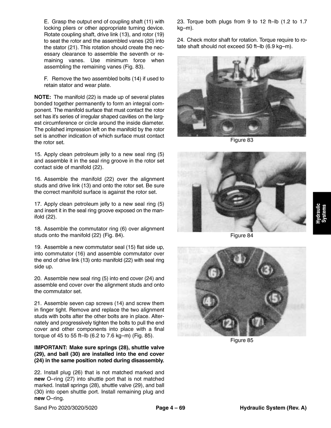
18.Assemble the commutator ring (6) over alignment studs onto the manifold (22) (Fig. 84).
19.Assemble a new commutator seal (15) flat side up, into commutator (16) and assemble commutator over the end of drive link (13) onto manifold (22) with seal ring side up.
20.Assemble new seal ring (5) into end cover (24) and assemble end cover over the alignment studs and onto the commutator set.
21.Assemble seven cap screws (14) and screw them in finger tight. Remove and replace the two alignment studs with bolts after the other bolts are in place. Alter- nately and progressively tighten the bolts to pull the end cover and other components into place with a final torque of 45 to 55
IMPORTANT: Make sure springs (28), shuttle valve (29), and ball (30) are installed into the end cover (24) in the same position noted during disassembly.
22.Install plug (26) that is not matched marked and new
23.Torque both plugs from 9 to 12
24.Check motor shaft for rotation. Torque require to ro- tate shaft should not exceed 50
Figure 83
Figure 84
Figure 85
Hydraulic | Systems |
|
|
Sand Pro 2020/3020/5020 | Page 4 – 69 | Hydraulic System (Rev. A) |