7.Remove three cap screws securing the pump plate to the hydrostat while pulling the pump plate from the hy- drostat (Fig. 32).
8.Clean all hydraulic fittings and hydraulic hoses at- tached to the hydrostat. Label all hydraulic connections for reassembly.
9.Place a suitable container under hydrostat to collect hydraulic oil.
10.Clamp suction hose (8) to prevent draining the hy- draulic tank.
11.Remove hydraulic hoses (11 and 14) from 90o hy- draulic fittings (13 and 12). Allow fluid to drain from the hoses into the container.
12.Remove suction hose (8) from push on fitting (10). Allow fluid to drain from the hose into the container.
13.Remove hydraulic hoses (4 and 5) and
14.Put caps or plugs on disconnected hoses and fit- tings to prevent contamination.
15.Loosen both set screws (20) from hydrostat shaft.
16.Support hydrostat to prevent dropping during re- moval. Remove both hex nuts (27), lock washers (28), cap screws (6) from the hydrostat (9) and pump mount (25). Pull hydrostat from mount and machine.
17.Remove woodruff key (26) from hydrostat shaft.
18.Match mark position of hydraulic fittings on the hy- drostat. Remove remaining fittings (10, 12, and 13) and
Installation (Fig. 31)
1.Make sure lift valve, hydraulic hoses, fittings, and tubes are cleaned thoroughly.
2.Reinstall
13) to the hydrostat. Observe match marks when tight- ening.
3.Remove caps or plugs from the hydrostat.
4.Install woodruff key (26) to hydrostat shaft. Support hydrostat (9) while positioning onto pump mount (25). Make sure woodruff key (26) stays in place when the shaft is inserted into the pump hub (24).
5.Secure hydrostat to mount with both cap screws (6), lock washers (28), hex nuts (27). Tighten set screw (20) to hydrostat shaft.
6.Remove caps and plugs from disconnected hoses and fittings.
7.Reinstall hydraulic hoses (11 and 14) to 90o hydrau- lic fittings (13 and 12).
8.Reinstall hose clamp (30) and suction hose (8) to push on fitting (10). Tighten hose clamp.
9.Remove clamp used to prevent draining the hydrau- lic tank from suction hose (8).
10.Reinstall hydraulic hoses (4 and 5) and
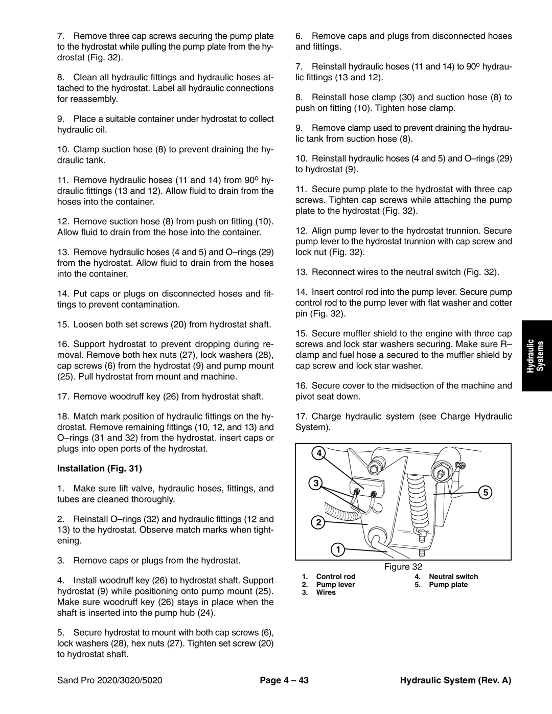
11.Secure pump plate to the hydrostat with three cap screws. Tighten cap screws while attaching the pump plate to the hydrostat (Fig. 32).
12.Align pump lever to the hydrostat trunnion. Secure pump lever to the hydrostat trunnion with cap screw and lock nut (Fig. 32).
13.Reconnect wires to the neutral switch (Fig. 32).
14.Insert control rod into the pump lever. Secure pump control rod to the pump lever with flat washer and cotter pin (Fig. 32).
15.Secure muffler shield to the engine with three cap screws and lock star washers securing. Make sure R– clamp and fuel hose a secured to the muffler shield by cap screw and lock star washer.
16.Secure cover to the midsection of the machine and pivot seat down.
17.Charge hydraulic system (see Charge Hydraulic System).
4
3
5
2 ![]()
1 ![]()
Figure 32
1. | Control rod | 4. | Neutral switch |
2. | Pump lever | 5. | Pump plate |
3.Wires
Hydraulic | Systems |
|
|
Sand Pro 2020/3020/5020 | Page 4 – 43 | Hydraulic System (Rev. A) |