10.Disconnect red positive cable cable (solenoid) from the starter (Fig. 47).
11.Remove lock nut and cap screw securing black ground wire and black battery cable (negative) to the en- gine block. Pull cable and harness clear of the engine (Fig. 47).
12.Remove remaining three lock nuts and cap screws securing the engine to its base.
CAUTION
Before jacking up the machine, review and follow Jacking Instructions in Chapter 1 – Safety.
One person should operate the jack while the other person guides the engine from the frame and engine base.
IMPORTANT: Make sure not to damage wires, wire harness, hoses, and cables while removing the en- gine from the machine.
13.Remove engine as follows (Fig. 43 and 48):
A.Position a jack under the rear of the engine base.
B.Support engine with a jack, then remove cap screws and flat washers securing the engine sup- port to the frame.
IMPORTANT: When the rear of the engine base is lowered, the base will pivot at the front engine mounts. Lower base about 1 inch (2.5 cm), which is enough to allow the top of the engine to clear the tra- verse rod. Avoid damaging the cooling fan and oil cooler as the hydrostat pivots up. The engine should then slide off the base. Do not allow engine to drop.
C.Lower rear of the engine base. Remove engine from the engine hub and base. Remove square key from the engine shaft.
14.Secure engine base and hydrostat to prevent the cooling fan from damaging the oil cooler.
Engine Installation (Fig. 43)
CAUTION
One person should operate the jack while the other person guides the engine into the frame.
IMPORTANT: Make sure not to damage the engine, fuel and hydraulic lines, electrical harness, or other parts while installing the engine.
1
|
|
| 2 |
| 5 |
|
|
|
| 4 | 3 |
|
|
| |
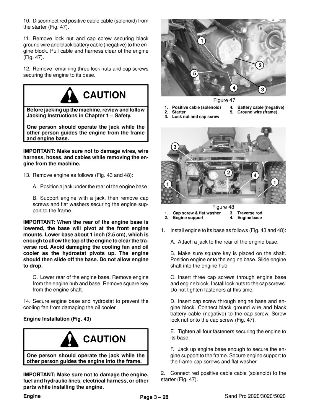
| Figure 47 |
| |
1. | Positive cable (solenoid) | 4. | Battery cable (negative) |
2. | Starter | 5. | Ground wire (frame) |
3. | Lock nut and cap screw |
|
|
3
|
| 2 | 4 |
|
|
| |
1 |
|
| 1 |
|
|
| |
| Figure 48 |
| |
1. | Cap screw & flat washer | 3. | Traverse rod |
2. | Engine support | 4. | Engine base |
1.Install engine to its base as follows (Fig. 43 and 48):
A.Attach a jack to the rear of the engine base.
B.Make sure square key is placed on the shaft. Position engine onto the engine base. Slide engine shaft into the engine hub
C.Insert three cap screws through engine base and engine block. Install lock nuts to the cap screws. Do not tighten fasteners at this time.
D.Insert cap screw through engine base and en- gine block. Connect black ground wire and black battery cable (negative) to the cap screw. Screw lock nut onto the cap screw (Fig. 47).
E.Tighten all four fasteners securing the engine to its base.
F.Jack up engine base enough to secure the en- gine support to the frame. Secure engine support to the frame cap screws and flat washer.
2.Connect red positive cable cable (solenoid) to the starter (Fig. 47).
Engine | Page 3 – 28 | Sand Pro 2020/3020/5020 |