NOTE: The brake lever, backing plate, retaining clip, return springs, brake shoes, and cam shaft can be re- moved as a complete brake assembly.
7.If it is desired to remove the brake assembly from the brake bracket, remove four cap screws and lock nuts securing the assembly to the bracket.
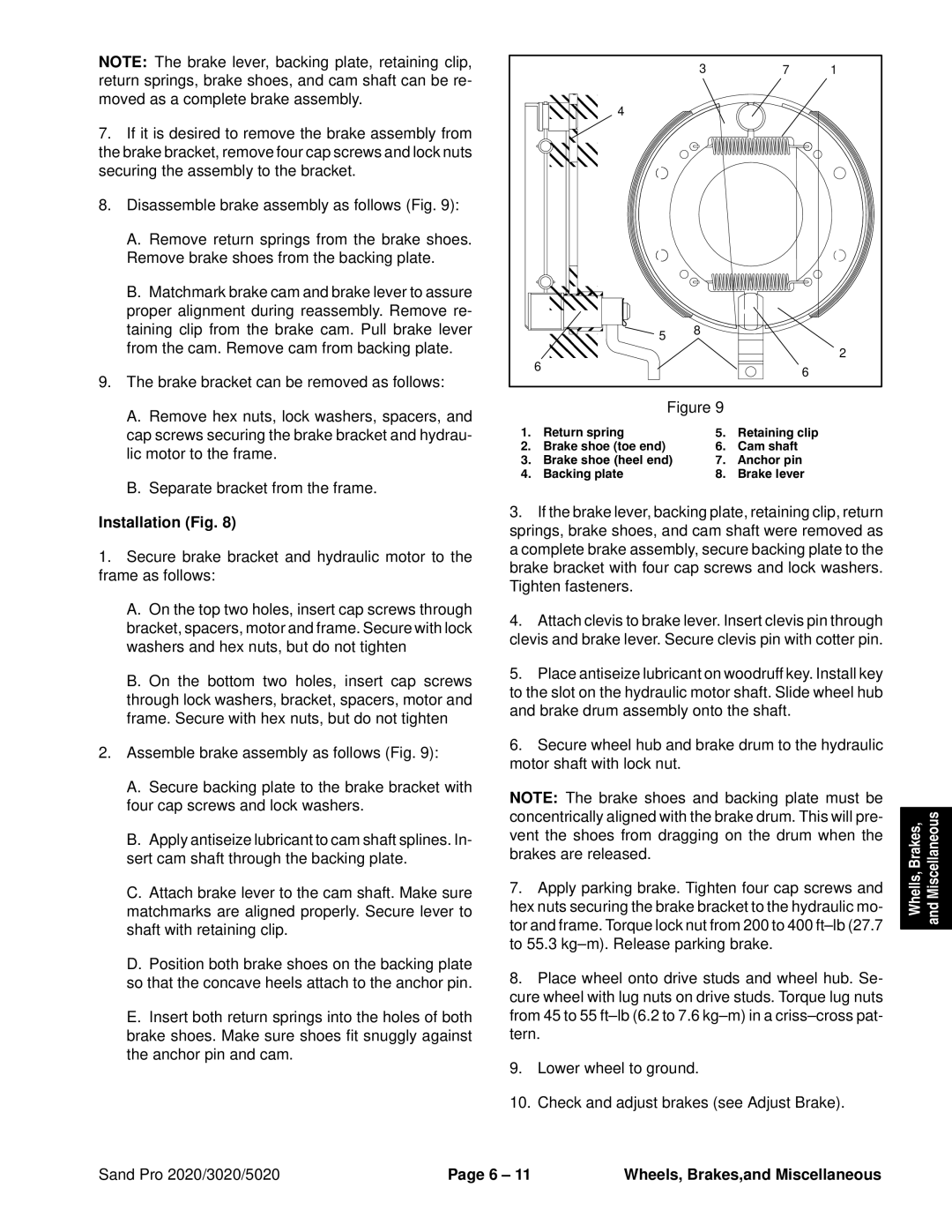
8.Disassemble brake assembly as follows (Fig. 9):
A.Remove return springs from the brake shoes. Remove brake shoes from the backing plate.
B.Matchmark brake cam and brake lever to assure proper alignment during reassembly. Remove re- taining clip from the brake cam. Pull brake lever from the cam. Remove cam from backing plate.
9.The brake bracket can be removed as follows:
A.Remove hex nuts, lock washers, spacers, and cap screws securing the brake bracket and hydrau- lic motor to the frame.
B.Separate bracket from the frame.
Installation (Fig. 8)
1.Secure brake bracket and hydraulic motor to the frame as follows:
A.On the top two holes, insert cap screws through bracket, spacers, motor and frame. Secure with lock washers and hex nuts, but do not tighten
B.On the bottom two holes, insert cap screws through lock washers, bracket, spacers, motor and frame. Secure with hex nuts, but do not tighten
2.Assemble brake assembly as follows (Fig. 9):
A.Secure backing plate to the brake bracket with four cap screws and lock washers.
B.Apply antiseize lubricant to cam shaft splines. In- sert cam shaft through the backing plate.
C.Attach brake lever to the cam shaft. Make sure matchmarks are aligned properly. Secure lever to shaft with retaining clip.
D.Position both brake shoes on the backing plate so that the concave heels attach to the anchor pin.
E.Insert both return springs into the holes of both brake shoes. Make sure shoes fit snuggly against the anchor pin and cam.
|
| 3 | 7 | 1 |
| 4 |
|
|
|
| 5 | 8 |
|
|
|
|
|
| |
| 6 |
|
| 2 |
|
| 6 |
| |
|
|
|
| |
| Figure 9 |
|
| |
1. | Return spring | 5. | Retaining clip |
|
2. | Brake shoe (toe end) | 6. | Cam shaft |
|
3. | Brake shoe (heel end) | 7. | Anchor pin |
|
4. | Backing plate | 8. | Brake lever |
|
3. | If theÇÇbrake lever, backing plate, retaining clip, return | |||
springs, brake shoes, and cam shaft were removed as | ||||
a completeÇÇbrake assembly, secure backing plate to the brake bracket with four cap screws and lock washers. Tighten fasteners.
4. Attach clevis to brake lever. Insert clevis pin through clevis and brake lever. Secure clevis pin with cotter pin.
5. Place antiseize lubricant on woodruff key. Install key to the slot on the hydraulic motor shaft. Slide wheel hub and brake drum assembly onto the shaft.
6. Secure wheel hub and brake drum to the hydraulic motor shaft with lock nut.
NOTE: The brake shoes and backing plate must be concentrically aligned with the brake drum. This will pre- vent the shoes from dragging on the drum when the brakes are released.
7.Apply parking brake. Tighten four cap screws and hex nuts securing the brake bracket to the hydraulic mo- tor and frame. Torque lock nut from 200 to 400
8.Place wheel onto drive studs and wheel hub. Se- cure wheel with lug nuts on drive studs. Torque lug nuts from 45 to 55
9.Lower wheel to ground.
10.Check and adjust brakes (see Adjust Brake).
Whells, Brakes, and Miscellaneous
Sand Pro 2020/3020/5020 | Page 6 – 11 | Wheels, Brakes,and Miscellaneous |