5.Disconnect air hose from the air cleaner. Remove lower shroud from the cooler mount to prevent damage to the fan when removing the hydrostat.
6.Disconnect control rod from pump lever and wires from the neutral switch (Fig. 36).
7.Loosen both set screws (11) on the pump hub (19) enough to allow the hydrostat shaft to be released.
8.Clamp hydraulic hose (35) and hydraulic hose (25) to prevent draining of the tank. Disconnect all six hy- draulic hoses from fittings on the hydrostat. Allow hoses to drain into a suitable container.
9.Remove self tapping screw securing
1
3
4![]()
2
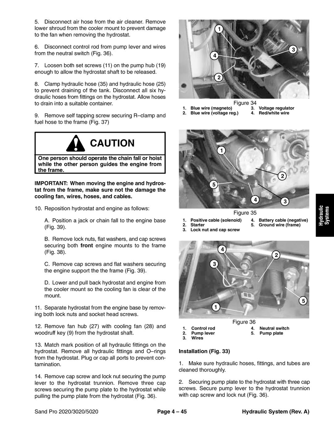
Figure 34
1. | Blue wire (magneto) | 3. | Voltage regulator |
2. | Blue wire (voltage reg.) | 4. | Red/white wire |
![]() CAUTION
CAUTION
One person should operate the chain fall or hoist while the other person guides the engine from the frame.
IMPORTANT: When moving the engine and hydros- tat from the frame, make sure not the damage the cooling fan, wires, hoses, and cables.
10.Reposition hydrostat and engine as follows:
A.Position a jack or chain fall to the engine base (Fig. 39).
B.Remove lock nuts, flat washers, and cap screws securing both front engine mounts to the frame (Fig. 38).
C.Remove cap screws and flat washers securing the engine support the the frame (Fig. 39).
D.Lower and pull back hydrostat and engine from the cooler mount so the cooling fan is clear of the mount.
11.Separate hydrostat from the engine base by remov- ing both lock nuts and socket head screws.
12.Remove fan hub (27) with cooling fan (28) and woodruff key (9) from the hydrostat shaft.
13.Match mark position of all hydraulic fittings on the hydrostat. Remove all hydraulic fittings and
14.Remove cap screw and lock nut securing the pump lever to the hydrostat trunnion. Remove three cap screws securing the pump plate to the hydrostat while pulling the pump plate from the hydrostat (Fig. 36).
1
|
|
| 2 |
| 5 |
|
|
|
| 4 | 3 |
|
|
| |
| Figure 35 |
| |
1. | Positive cable (solenoid) | 4. | Battery cable (negative) |
2. | Starter | 5. | Ground wire (frame) |
3. | Lock nut and cap screw |
|
|
4
2
3
5
1
Figure 36
1. | Control rod | 4. | Neutral switch |
2. | Pump lever | 5. | Pump plate |
3.Wires
Installation (Fig. 33)
1.Make sure hydraulic hoses, fittings, and tubes are cleaned thoroughly.
2.Securing pump plate to the hydrostat with three cap screws. Secure pump lever to the hydrostat trunnion with cap screw and lock nut (Fig. 36).
Hydraulic | Systems |
|
|
Sand Pro 2020/3020/5020 | Page 4 – 45 | Hydraulic System (Rev. A) |