Traction Pump Inspection
1.Inspect end cap (Fig. 45).
A.Bearing needles must remain in the cage, roll freely, and not be bent or damaged. Remove and re- place bearings as necessary.
B.Journal bearing must be free of damage.
C.Needle and journal bearings should protrude be- yond face from 3/32 to 1/8 inch (2.38 to 3.18 mm).
2.Inspect valve plate. There should be no signs of scoring on contact surfaces (Fig. 45).
NOTE: The pistons may slide out of the cylinder block. Piston placement in the bores requires no special orien- tating. Do not disassemble spring or other parts from the center bore of the cylinder block.
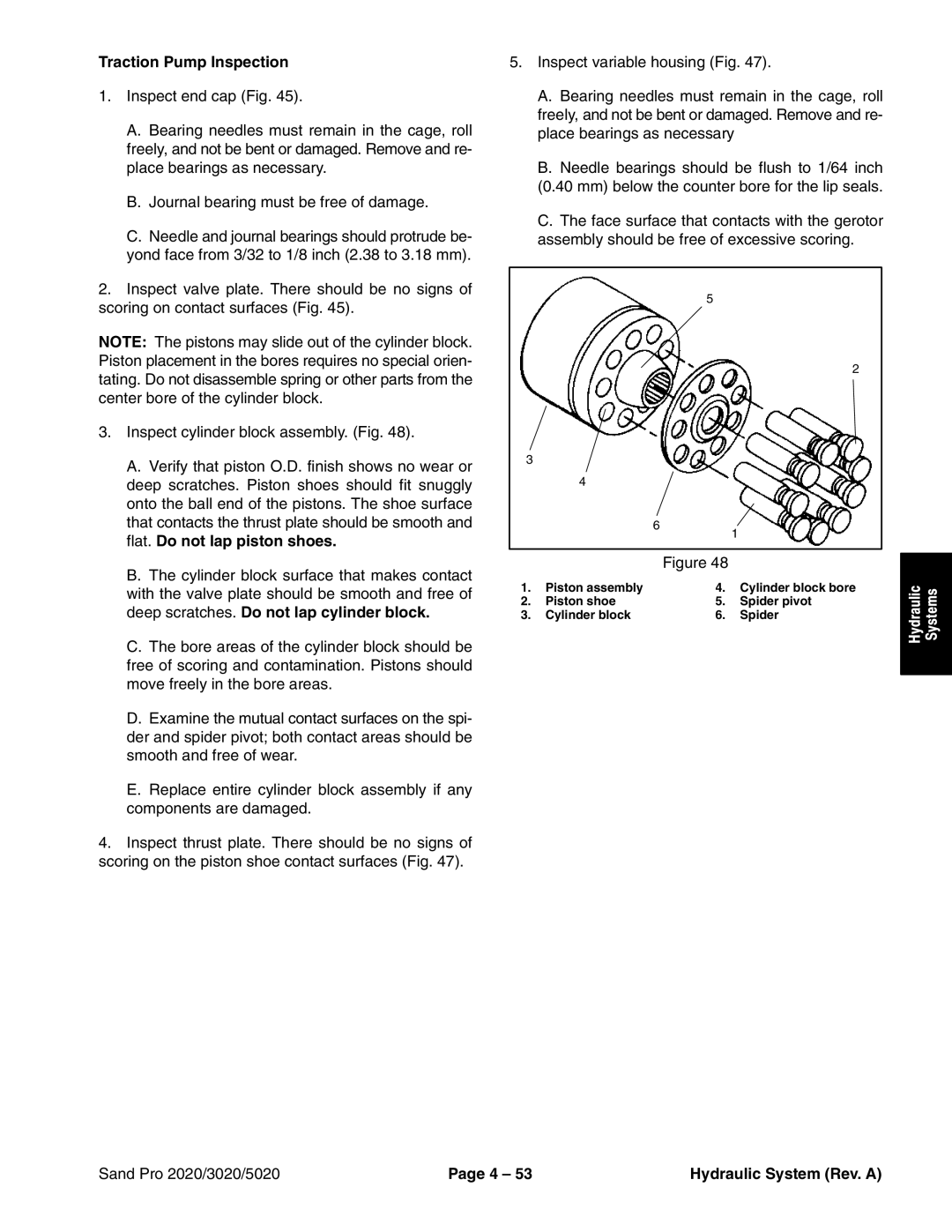
3.Inspect cylinder block assembly. (Fig. 48).
A.Verify that piston O.D. finish shows no wear or deep scratches. Piston shoes should fit snuggly onto the ball end of the pistons. The shoe surface that contacts the thrust plate should be smooth and flat. Do not lap piston shoes.
B.The cylinder block surface that makes contact with the valve plate should be smooth and free of deep scratches. Do not lap cylinder block.
C.The bore areas of the cylinder block should be free of scoring and contamination. Pistons should move freely in the bore areas.
D.Examine the mutual contact surfaces on the spi- der and spider pivot; both contact areas should be smooth and free of wear.
E.Replace entire cylinder block assembly if any components are damaged.
4.Inspect thrust plate. There should be no signs of scoring on the piston shoe contact surfaces (Fig. 47).
5.Inspect variable housing (Fig. 47).
A.Bearing needles must remain in the cage, roll freely, and not be bent or damaged. Remove and re- place bearings as necessary
B.Needle bearings should be flush to 1/64 inch (0.40 mm) below the counter bore for the lip seals.
C.The face surface that contacts with the gerotor assembly should be free of excessive scoring.
5
2
3
4
6![]()
1
Figure 48
1. | Piston assembly | 4. | Cylinder block bore |
2. | Piston shoe | 5. | Spider pivot |
3. | Cylinder block | 6. | Spider |
Hydraulic | Systems |
|
|
Sand Pro 2020/3020/5020 | Page 4 – 53 | Hydraulic System (Rev. A) |