![]() CAUTION
CAUTION
One person should operate the chain fall or jack while the other person guides the engine and hy- drostat from the frame.
IMPORTANT: When moving the engine and hydros- tat from the frame, make sure not the damage the cooling fan, wires, hoses, and cables.
6.Reposition hydrostat and engine as follows:
A.Position a jack or chain fall to the engine base.
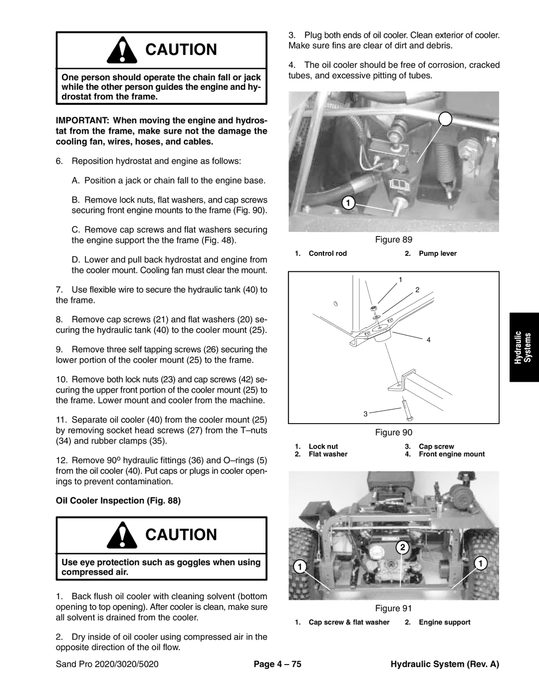
B.Remove lock nuts, flat washers, and cap screws securing front engine mounts to the frame (Fig. 90).
C.Remove cap screws and flat washers securing the engine support the the frame (Fig. 48).
D.Lower and pull back hydrostat and engine from the cooler mount. Cooling fan must clear the mount.
7.Use flexible wire to secure the hydraulic tank (40) to the frame.
8.Remove cap screws (21) and flat washers (20) se- curing the hydraulic tank (40) to the cooler mount (25).
9.Remove three self tapping screws (26) securing the lower portion of the cooler mount (25) to the frame.
10.Remove both lock nuts (23) and cap screws (42) se- curing the upper front portion of the cooler mount (25) to the frame. Lower mount and cooler from the machine.
11.Separate oil cooler (40) from the cooler mount (25) by removing socket head screws (27) from the
12.Remove 90o hydraulic fittings (36) and
Oil Cooler Inspection (Fig. 88)
![]() CAUTION
CAUTION
Use eye protection such as goggles when using compressed air.
1.Back flush oil cooler with cleaning solvent (bottom opening to top opening). After cooler is clean, make sure all solvent is drained from the cooler.
2.Dry inside of oil cooler using compressed air in the opposite direction of the oil flow.
3.Plug both ends of oil cooler. Clean exterior of cooler. Make sure fins are clear of dirt and debris.
4.The oil cooler should be free of corrosion, cracked tubes, and excessive pitting of tubes.
2
1
Figure 89
1. Control rod | 2. Pump lever |
1
2
4
3
Figure 90
1. | Lock nut | 3. | Cap screw |
2. | Flat washer | 4. | Front engine mount |
| 2 |
1 | 1 |
| |
Figure 91 | |
1. Cap screw & flat washer | 2. Engine support |
Hydraulic | Systems |
|
|
Sand Pro 2020/3020/5020 | Page 4 – 75 | Hydraulic System (Rev. A) |