Toro Company 1998, 2003
Preface
Sand Pro 2020/3020/5020
Table Of Contents
Sand Pro 2020/3020/5020
Sand Pro 2020/3020/5020 Safety
General Safety Instructions
Chapter
Before Operating
While Operating
Safety Sand Pro 2020/3020/5020
Maintenance and Service
Jacking Instructions
Jacking the Front End
Jacking the Rear End
On Valve Shroud Part No
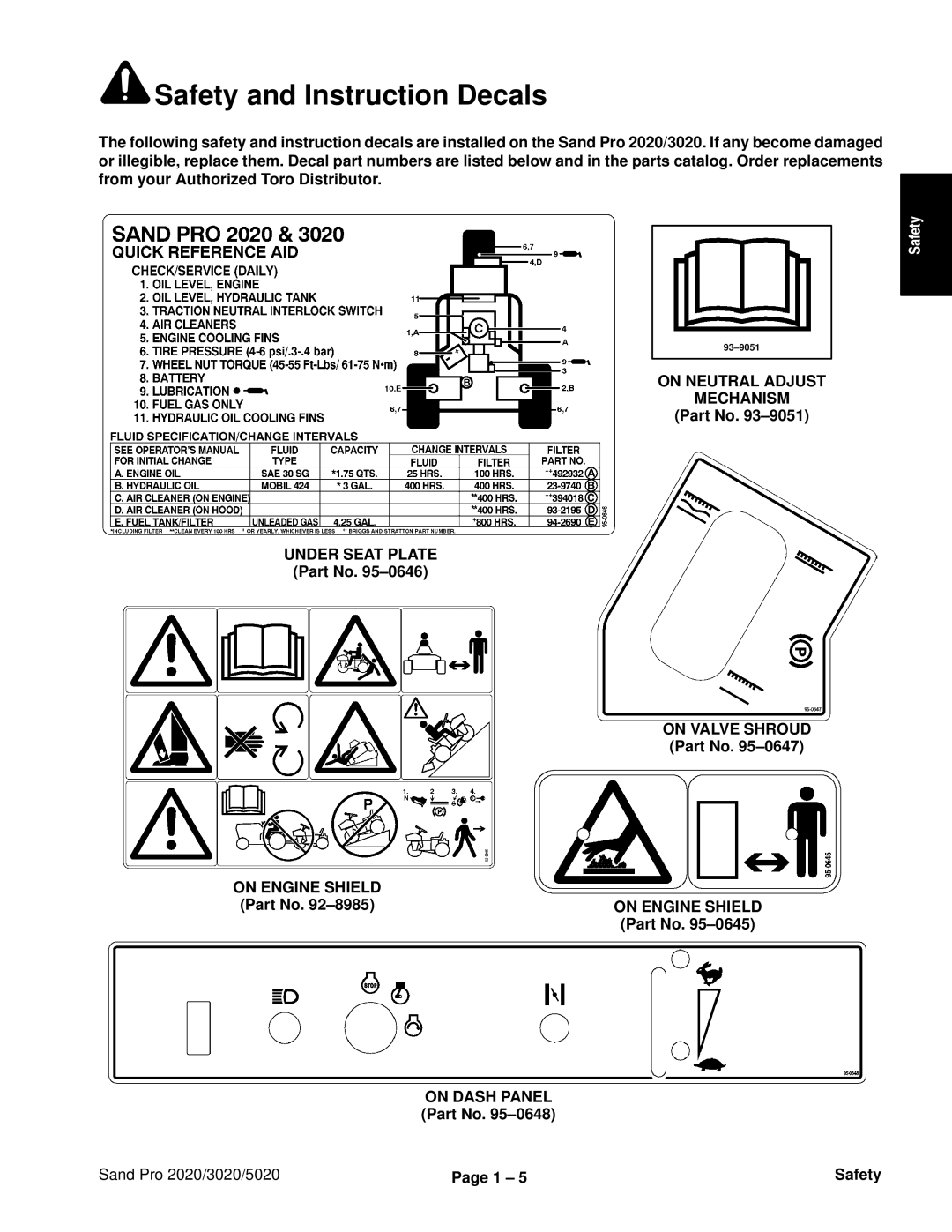
Safety and Instruction Decals
Safety and Instruction Decals
Product Records
Sand Pro 2020/3020/5020 Product Records and Maintenance
Equivalents and Conversions
Product Records and Maintenance Sand Pro 2020/3020/5020
Torque Specifications
Sand Pro 2020/3020 Early Models
Lubrication
Sand Pro 2020/3020 Late Models
Sand Pro
Sand Pro 2020/3020/5020 Product Records and Maintenance
Product Records and Maintenance Sand Pro 2020/3020/5020
Equipment Operation and Service History Report
Annual Recommendations
Minimum Recommended Maintenance Intervals
Notation for areas of concern
Maintenance Daily Maintenance Check For Week Check Item b
Supervisor
B Sevice required
Sand Pro 2020/3020/5020 Engine
Engine
Engine Sand Pro 2020/3020/5020
Introduction
Description
Specifications
Check Engine Oil
General Information
Fuel Shutoff Valve
Fill Fuel Tank
Clean area around fuel tank cap Remove fuel tank cap
Adjustments
Adjust Throttle Control
Adjust Choke Control
Service and Repairs
Service Engine Air Cleaner
Change Engine Oil and Filter
Use eye protection such as goggles when using compressed air
Service Remote Air Cleaner
Throttle Control Removal
Throttle and Choke Controls
Choke Control Removal
Throttle Control Installation
Replace Fuel Filter
Choke Control Installation
Remote Air Cleaner SP 2020/3020
Remote Air Cleaner Removal
Remote Air Cleaner Installation
Remote Air Cleaner SP
Muffler Installation
Muffler SP
Muffler Removal
Muffler SP 2020/3020
Cap screw & star washer
Fuel Tank SP 2020/3020
Fuel Tank Removal Fig
Fuel Tank installation Fig
Fuel Tank SP
Adjustment lever Cap screw Tilt lock pin
Engine SP 2020/3020
Engine Removal Fig
Cap screw & lock washer 3. Engine block
Inch 762 mm
Replace Spark Plugs
Engine SP
Cotter pin & flat washer Lock nut Seat rod
Positive cable solenoid
Engine
Clean Cylinder Head Fins
Sand Pro 2020/3020/5020 Hydraulic System Rev. a
Hydraulic Systems
Hydraulic System 4 2 Rev. B Sand Pro 2020/3020/5020
Hydraulic Fitting Installation
Hydraulic Hoses
Ring Face Seal
SAE Straight Thread O-Ring Port Non-adjustable
SAE Straight Thread O-Ring Port Adjustable
Hydraulic System Rev. a Sand Pro 2020/3020/5020
Towing Traction Unit
Check Hydraulic System Fluid
ISO type 46/68 anti-wear hydraulic fluid
Hydraulic
Hydraulic Schematic
Hydraulic System
Rev. a
Traction Forward
Hydraulic Flow Diagrams
High Pressure Low Pressure Charge Return or Suction Flow
Traction Forward
Traction Reverse
Traction Reverse
Retract and Extend Lift Cylinder
Extend and Retract lift Cylinder
Special Tools
Hydraulic Pressure Test Kit TOR47009
Hydraulic Tester Pressure and Flow TOR214678
Hydraulic Test Fittings
Hydraulic Test Fitting Kit TOR4079
Troubleshooting
Problem
Hydraulic System 4 16 Rev. B Sand Pro 2020/3020/5020
Hydraulic Systems
Hydraulic System Rev. a 4 18 Rev. B Sand Pro 2020/3020/5020
Before Performing Hydraulic Tests
Testing
Test no Traction Pump Flow P1
Procedure for Traction Pump Flow P1
Charge test port SP 2020/3020 Engine base plate SP 2020/3020
4 23 Rev. B Hydraulic System Rev. a
Test no Charge Pump P2 Flow
Procedure for Charge Pump P2 Flow
Test no Wheel Motor Efficiency
Make sure the tester flow control valve is fully open
Procedure for Wheel Motor Efficiency
Adjust Traction Pedal for Forward SP 2020/3020
Adjust Traction Pedal for Neutral
Adjust Traction Pedal for Forward SP
Adjust Lift Lever SP
Adjust Lift Lever SP 2020/3020
Charge Hydraulic System
Check Hydraulic Lines and Hoses
Hydraulic System Rev. a Sand Pro 2020/3020/5020
Change Hydraulic System Fluid and Filter
Lift Valve SP 2020/3020
Removal Fig
Installation Fig
Lift Valve SP
Removal Fig
Reassembly
Disassembly
Lift Valve
Inspection
Installation
Lift Cylinder SP 2020/3020
Removal
Lift CylinderSP
Lift Cylinder Service
Right Front
Hydrostat SP 2020/3020
Pump lever Pump plate Wires
Hydrostat SP
Blue wire magneto
Clamp Fuel hose
Flush Hydraulic System
Hydraulic System Rev. a 4 48 Rev. B Sand Pro 2020/3020/5020
Hydrostat Service
Charge Pump Disassembly
Charge Pump Assembly
Charge Pump Inspection
Shaft Seal Removal
Shaft Seal Installation
Relief Valve Disassembly Fig
Acceleration Valve Assembly Fig
Relief Valve Assembly Fig
Charge Check Valve Disassembly Fig
Position variable housing so the large cavity faces up Fig
Traction Pump Disassembly
Traction Pump Inspection
Traction Pump Assembly
Cap screw 4 used
Front Wheel Motor
Installation Fig
250 to 400 ft-lb 34.6 to 55.3 kg-m
Rear Wheel Motors SP 2020/3020
Removal or
Installation or
Rear Wheel Motors SP
Removal or
Wheel Motor Service
Use eye protection such as goggles when using compressed air
Inspection Fig
Sand Pro 2020/3020/5020 Hydraulic System Rev. a
Assembly Fig
Sand Pro 2020/3020/5020 Hydraulic System Rev. a
Hydraulic System Rev. a
Sand Pro 2020/3020/5020 Hydraulic System Rev. a
30 to 60 ft-lb 35 to 69 kg-cm
Hydraulic Tank SP 2020/3020
Removal Fig
Hydraulic Oil Cooler SP 2020/3020
Cleaning and Inspection Fig
Oil Cooler Removal Fig
Hydraulic Tank and Oil Cooler SP
Control rod Pump lever Lock nut Cap screw Flat washer
Hydraulic Tank Installation Fig
Oil Cooler Installation Fig
Hydraulic Tank Removal Fig
Hydraulic Tank Inspection Fig
Sand Pro 2020/3020/5020 Electrical Systems
Electrical Systems
Diagrams
Electrical Schematics
Electrical Schematic
Sand Pro 2020/3020
Wire Identification
Harness and Wiring Diagram
Sand Pro
SP2
Multimeter
Skin-Over Grease
Electrical Systems Sand Pro 2020/3020/5020
Problem Possible Causes
Starting Problems
General Run and Transport Problems
Battery Test Open Circuit Test
Voltage Measured Battery Charge Level
Electrical System Quick Checks
Ignition Switch
Component Testing
SP 2020/3020
Hour Meter
Neutral Switch
Starter Solenoid
Ohms
Battery Care
Battery Storage
Battery Specifications
Battery Service
Toro
Inspection, Maintenance, and Testing Fig
Battery Charge Specific Open Circuit
Minimum Battery Electrolyte
Charging
Gravity Voltage
Check Interlock System
Optional Lights
Sand Pro 2020/3020/5020 Wheels, Brakes,and Miscellaneous
Wheels, Brakes, and Miscellaneous
Wheels, Brakes, and Miscellaneous Sand Pro 2020/3020/5020
Adjust Steering Chain
Adjust Brake SP
Adjust Brake SP 2020/3020
Seat SP 2020/3020
Front Wheel SP
Installation Fig
Front Wheel SP 3020 and SP
Installation Fig
Rear Wheels and Brakes
Brake shoe toe end
Right Front
Brake Linkages SP 2020/3020
Brake Linkages SP
Front Fork and Steering SP 2020 and Older SP 3020 Models
Front Fork and Steering Newer SP 3020 Models
Upper Steering Assembly
Upper Steering Disassembly
Lower Steering Disassembly
Lower Steering Assembly
Front Fork Removal
Wheels, Brakes, and Miscellaneous Sand Pro 2020/3020/5020
Seat SP
Steering SP
Upper Steering Assembly Fig
Upper Steering Disassembly Fig
Front Fork SP
Hood and Dash Panel SP 2020/3020
Right Fender Installation
Seat Base Installation Fig
Fenders SP
Left FenderSeat Base Removal Fig
Page
Commercial Products


 Safety and Instruction Decals