Lower Steering Disassembly (Fig. 13 and 14)
NOTE: If disassembly of the steering mechanism be- low the steering knuckle is required, proceed as follows:
1.Loosen lock nut on the steering adjustment pin enough to loosen the steering chain from the sprocket. Remove chain from sprocket.
2.Remove
3.Drive out roll pin securing lower steering shaft to steering knuckle with drift punch.
4.If it is required to remove the steering knuckle at this time, drive out roll pin securing upper steering shaft to the steering knuckle with drift punch.
5.Pull lower steering shaft from the frame and steering knuckle. If required, pull steering knuckle from the upper steering shaft.
Lower Steering Assembly (Fig. 13 and 14)
1.If removed, secure steering knuckle to the upper steering shaft withroll pin.
2.Position lower steering shaft through the frame and into the steering knuckle. Align holes and secure shaft to the steering knuckle with roll pin.
3.Secure sprocket to the lower steering shaft with new
4.Position steering chain around the sprocket and chain guide. Secure chain to chain bracket with steering adjustment pins and lock nuts. Adjust steering chain (see Adjust Steering Chain).
Front Fork Removal (Fig. 13 and 14))
NOTE: If disassembly of the front fork and its bearings is required, proceed as follows:
![]() WARNING
WARNING
Before jacking up the machine, review and follow Jacking Instructions in Chapter 1 – Safety.
1.Jack up front wheel enough to allow removal of the front fork.
2.Remove cotter pin securing the slotted nut to the fork shaft. Unscrew slotted nut from the shaft. Remove steering washer from the shaft.
2
1
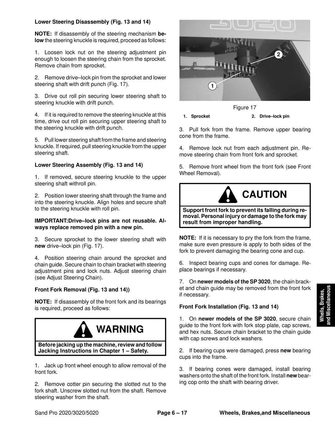
Figure 17
1. Sprocket | 2. |
3.Pull fork from the frame. Remove upper bearing cone from the frame.
4.Remove lock nut from each adjustment pin. Re- move steering chain from front fork and sprocket.
5.Remove front wheel from the front fork (see Front Wheel Removal).
CAUTION
Support front fork to prevent its falling during re- moval. Personal injury or damage to the fork may result from improper handling.
NOTE: If it is necessary to pry the fork from the frame, make sure even pressure is apply to both sides of the fork to prevent damaging the bearing cone and cup.
6.Inspect bearing cups and cones for damage. Re- place bearings if necessary.
7.On newer models of the SP 3020, the chain brack- et and chain guide may be removed from the front fork if necessary.
Front Fork Installation (Fig. 13 and 14)
1.On newer models of the SP 3020, secure chain guide to the front fork with fork stop plate, cap screws, and hex nuts. Secure chain bracket to the chain guide with cap screws and lock washers.
2.If bearing cups were damaged, press new bearing cups into the frame.
3.If bearing cones were damaged, install bearing washers onto the shaft of the front fork. Install new bear- ing cop onto the shaft with bearing driver.
Whells, Brakes, and Miscellaneous
Sand Pro 2020/3020/5020 | Page 6 – 17 | Wheels, Brakes,and Miscellaneous |