DataTalker Owner’s Manual
7.6Composite Link Settings - Internal ISDN Terminal Adapter
Table 7-6. Composite Link Settings - Internal ISDN Terminal Adapter
Step Procedure
1Toggle DIP switch position 3 to the down (closed) position to enable the command port.
2Connect a terminal or PC running communications software to the DATA/COMMAND connector on the back panel of the DataTalker.
Note: Any cables connected to the computer should be shielded to reduce interference.
3Apply power to the DataTalker.
4Apply power to the terminal or PC. Run the PC’s communications software in terminal mode and press ENTER twice to establish communications with the DataTalker. The Main Menu appears:
Main Menu
1 - Configurations
2 - Statistics
3 - Reset Options
4 - Diagnostics
5 - Exit Command Mode
6 - QUICK SETUP
Selection : _
5 Enter 1 and press ENTER. The Configurations menu is displayed:
Configurations
1 - Data Port Configuration
2 - Voice/Fax Channel(s) Configuration
3 - Composite Link Configuration
4 - Factory Default Configuration Options
5 - Configure Remote Unit
S - Store All Configurations
M - Main Menu
P - Previous Menu
Selection : _
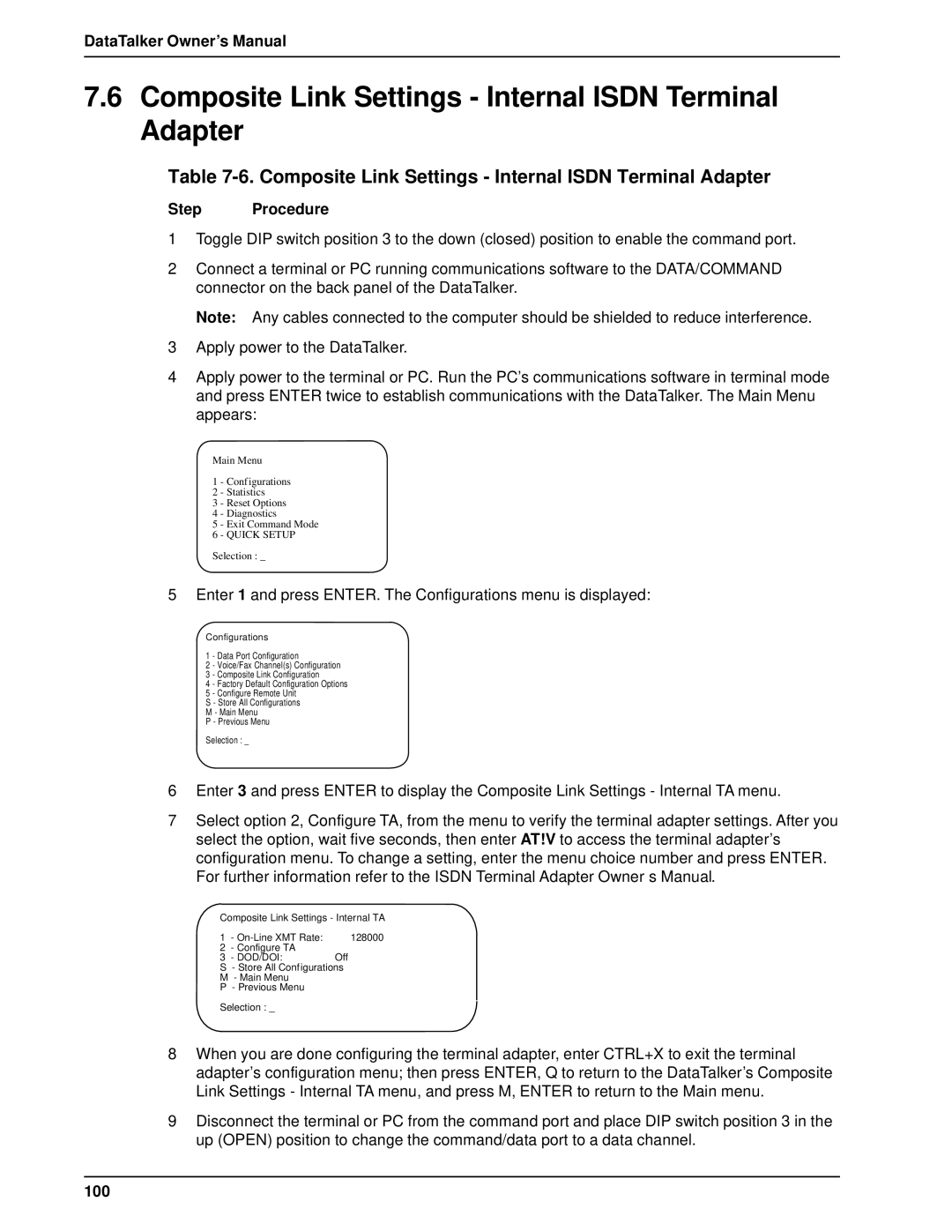
6Enter 3 and press ENTER to display the Composite Link Settings - Internal TA menu.
7Select option 2, Configure TA, from the menu to verify the terminal adapter settings. After you select the option, wait five seconds, then enter AT!V to access the terminal adapter’s configuration menu. To change a setting, enter the menu choice number and press ENTER. For further information refer to the ISDN Terminal Adapter Owner’s Manual.
Composite Link Settings - Internal TA
1 | - | 128000 |
2 | - Configure TA |
|
3 | - DOD/DOI: | Off |
S- Store All Configurations M - Main Menu
P - Previous Menu
Selection : _
8When you are done configuring the terminal adapter, enter CTRL+X to exit the terminal adapter’s configuration menu; then press ENTER, Q to return to the DataTalker’s Composite Link Settings - Internal TA menu, and press M, ENTER to return to the Main menu.
9Disconnect the terminal or PC from the command port and place DIP switch position 3 in the up (OPEN) position to change the command/data port to a data channel.