2.1.3 CHANNEL CONNECTORS
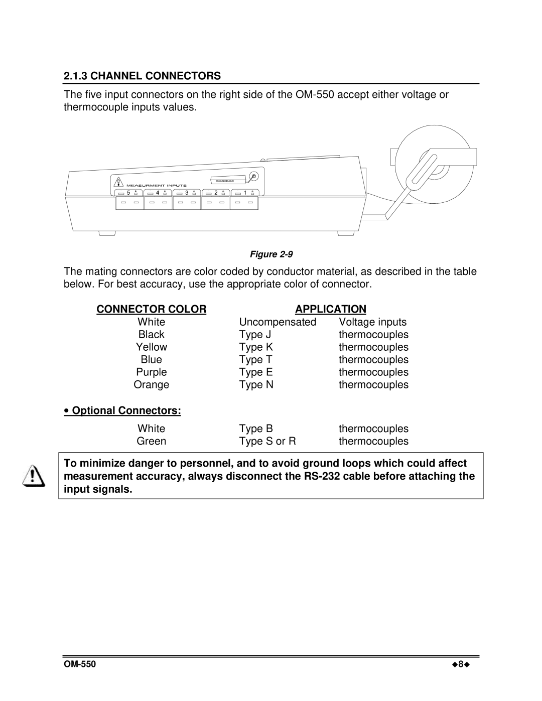
The five input connectors on the right side of the
Figure
The mating connectors are color coded by conductor material, as described in the table below. For best accuracy, use the appropriate color of connector.
CONNECTOR COLOR | APPLICATION | |
White | Uncompensated | Voltage inputs |
Black | Type J | thermocouples |
Yellow | Type K | thermocouples |
Blue | Type T | thermocouples |
Purple | Type E | thermocouples |
Orange | Type N | thermocouples |
∙Optional Connectors:
White | Type B | thermocouples |
Green | Type S or R | thermocouples |
To minimize danger to personnel, and to avoid ground loops which could affect measurement accuracy, always disconnect the
u8u |