2.3 INPUTS
As previously discussed, the
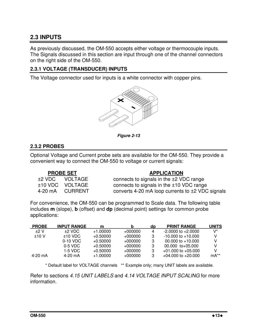
2.3.1 VOLTAGE (TRANSDUCER) INPUTS
The Voltage connector used for inputs is a white connector with copper pins.
Figure
2.3.2 PROBES
Optional Voltage and Current probe sets are available for the
PROBE SET
±2 VDC | VOLTAGE |
±10 VDC | VOLTAGE |
CURRENT |
APPLICATION
connects to signals in the ±2 VDC range connects to signals in the ±10 VDC range converts
For convenience, the
PROBE | INPUT RANGE | m | b | dp | PRINT RANGE | UNITS |
±2 V | ±2 VDC | +1.00000 | +000000 | 4 | V* | |
±10 V | ±10 VDC | +0.50000 | +000000 | 3 | V | |
| +0.50000 | +000000 | 3 | 00.000 to +10.000 | V | |
| +0.50000 | +000000 | 3 | 00.000 to+05.000 | V | |
| +0.50000 | +000000 | 3 | +01.000 to +05.000 | V | |
+1.00000 | +000000 | 3 | +04.000 to +20.000 | mA** | ||
* Default label for VOLTAGE channels | ** Example only; many UNIT labels are available. | |||||
Refer to sections 4.15 UNIT LABELS and 4.14 VOLTAGE INPUT SCALING for more information.
u13u |