Parts and Their Functions
Front panel
|
|
|
|
|
|
|
|
|
|
|
|
|
|
|
|
|
|
| Y Z [ |
|
|
| |||
|
|
|
|
|
|
|
|
|
|
|
|
|
|
|
|
|
|
|
|
|
|
|
|
| EJECT |
|
|
|
|
|
|
|
|
|
|
|
|
|
|
|
|
|
|
|
|
|
|
|
| ||
POWER OFF |
|
|
| ON |
|
|
|
|
|
|
|
|
|
|
|
|
|
| Do not insert |
|
|
|
| ||
|
|
|
|
|
|
|
|
|
|
|
|
|
|
|
|
| without adapter |
|
|
|
| ||||
|
|
|
|
|
| CH1 | 2 | 3 | 4 | 5 | 6 | 7 | 8 | CUE |
|
|
|
|
|
|
|
|
|
|
|
|
|
|
|
| CH CONDITION |
| MONITOR | FULL/FINE 9P | REMOTE |
|
|
|
|
|
|
|
|
|
|
| |||||
|
|
|
|
|
| 50P |
|
|
|
|
|
|
|
|
|
| |||||||||
|
|
|
|
|
|
|
| L |
|
| R |
|
|
|
|
|
|
|
|
|
|
|
|
|
|
| HEADPHONES |
|
|
|
|
|
|
|
|
|
|
|
|
|
|
|
|
|
|
|
|
|
| ||
|
|
|
|
|
|
|
|
|
|
|
|
|
|
|
|
|
|
| HOME | RF1 | RF2 ASSEM | ADJUST | SHTL | JOG | VAR |
|
|
|
|
|
|
|
|
|
|
|
|
|
|
|
|
|
|
|
|
|
| ||||
|
|
|
|
|
|
|
|
|
|
|
|
|
|
|
|
|
|
| VIDEO UNITY | TC | CUE |
|
|
|
|
|
|
|
|
|
|
|
|
|
|
|
|
|
|
|
|
|
|
|
|
| INSERT |
| REV |
| FWD |
|
|
|
|
|
|
|
|
|
|
|
|
|
|
|
|
|
|
| AUDIO UNITY | DIAG | MENU |
|
| ||
|
|
|
|
|
|
|
|
|
|
|
|
|
|
|
|
|
|
| STAND BY | PLAYER RECORDER | INPUT CHECK |
|
|
| |
|
|
|
|
|
|
|
|
|
| SHIFT | F1 |
| F2 | F3 | F4 | F5 | F6 |
|
| SERVO | REC INHIBIT |
|
|
| |
|
|
|
|
|
| AUDIO CH SELECT |
|
|
|
|
|
|
|
| A IN | A OUT | EDIT |
|
|
|
| ||||
|
|
|
|
|
|
|
| ABC | DEF | GHI |
|
|
|
| PLAY | REC |
|
|
| ||||||
| CH 1 | CH 5 | CH 2 | CH 6 | CH 3 | CH 7 | CH 4 | CH 8 |
|
| 7 | 8 | 9 |
| PREVIEW/ | PRE- |
|
|
|
|
|
|
|
|
|
|
|
|
|
|
|
|
|
|
|
| JKL | MNO | PQRS |
| REVIEW | ROLL |
|
|
|
|
|
|
|
|
|
|
|
|
|
|
|
|
|
|
|
| 4 | 5 | 6 | BS | AUTO |
|
|
|
|
|
|
|
|
| |
|
|
|
|
|
|
|
|
|
|
| TUV | WXYZ |
|
|
| TRIM | REW |
| STOP | FF |
|
|
| ||
|
|
|
|
|
|
|
|
|
|
| 1 | 2 | 3 | ENT |
| EDIT |
|
|
|
|
| ||||
|
|
|
|
|
|
|
|
|
|
|
|
|
| SET |
|
|
|
|
|
|
| ||||
|
|
|
| PUSH |
|
|
|
|
|
|
|
|
|
|
| IN |
| OUT |
|
|
|
|
|
| |
|
|
|
| LOCK |
|
|
|
|
| 0 | C | T | F |
|
|
|
|
|
|
|
|
| |||
FULL | REC | P8 | REC | P8 | REC | P8 | REC | P8 |
|
|
|
|
|
|
|
|
|
|
|
| FULL | ||||
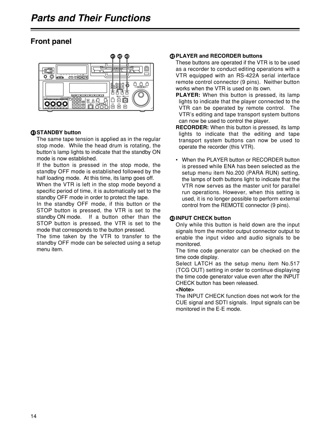
YSTANDBY button
The same tape tension is applied as in the regular stop mode. While the head drum is rotating, the button’s lamp lights to indicate that the standby ON mode is now established.
If the button is pressed in the stop mode, the standby OFF mode is established followed by the half loading mode. At this time, its lamp goes off.
When the VTR is left in the stop mode beyond a specific period of time, it is automatically set to the standby OFF mode in order to protect the tape.
In the standby OFF mode, if this button or the STOP button is pressed, the VTR is set to the standby ON mode. If a button other than the STOP button is pressed, the VTR is set to the mode that corresponds to the button pressed.
The time taken by the VTR to transfer to the standby OFF mode can be selected using a setup menu item.
ZPLAYER and RECORDER buttons
These buttons are operated if the VTR is to be used as a recorder to conduct editing operations with a VTR equipped with an
PLAYER: When this button is pressed, its lamp lights to indicate that the player connected to the VTR can be operated by remote control. The VTR’s editing and tape transport system buttons can now be used to control the player.
RECORDER: When this button is pressed, its lamp lights to indicate that the editing and tape transport system buttons can now be used to operate the recorder (this VTR).
•When the PLAYER button or RECORDER button is pressed while ENA has been selected as the setup menu item No.200 (PARA RUN) setting, the lamps of both buttons light to indicate that the VTR now serves as the master unit for parallel run operations. However, when this setting is used, it is no longer possible to perform external control from the REMOTE connector (9 pins).
[INPUT CHECK button
Only while this button is held down are the input signals from the monitor output connector output to enable the input video and audio signals to be monitored.
The time code generator can be checked on the time code display.
Select LATCH as the setup menu item No.517 (TCG OUT) setting in order to continue displaying the time code generator value even after the INPUT CHECK button has been released.
<Note>
The INPUT CHECK function does not work for the CUE signal and SDTI signals. Input signals can be monitored in the
14