Parts and Their Functions
Time code display
6
4
SHIFT
5
F1
F2
F3
F4
F5
3
F6
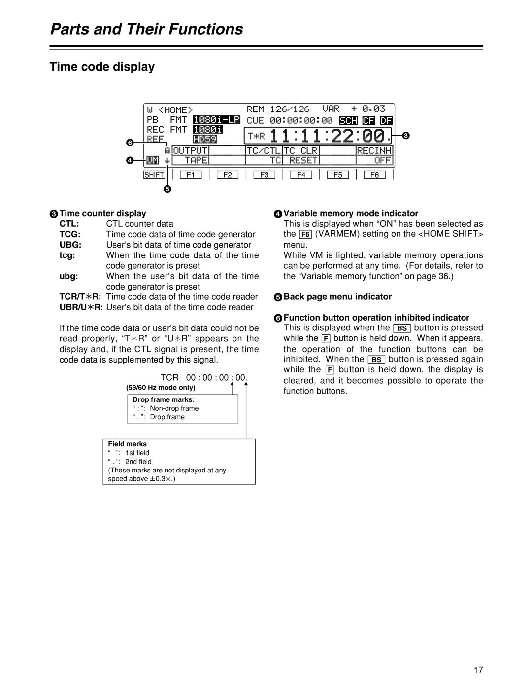
3Time counter display
CTL: CTL counter data
TCG: Time code data of time code generator
UBG: User’s bit data of time code generator
tcg: When the time code data of the time code generator is preset
ubg: When the user’s bit data of the time code generator is preset
TCR/T¢R: Time code data of the time code reader
UBR/U¢R: User’s bit data of the time code reader
If the time code data or user’s bit data could not be read properly, “T¢R” or “U¢R” appears on the display and, if the CTL signal is present, the time code data is supplemented by this signal.
TCR 00 : 00 : 00 : 00.
(59/60 Hz mode only)
Drop frame marks:
“: ”:
“. ”: Drop frame
Field marks
“”: 1st field
“. ”: 2nd field
(These marks are not displayed at any speed above w0.3k.)
4Variable memory mode indicator
This is displayed when “ON” has been selected as the F6 (VARMEM) setting on the <HOME SHIFT> menu.
While VM is lighted, variable memory operations can be performed at any time. (For details, refer to the “Variable memory function” on page 36.)
5Back page menu indicator
6Function button operation inhibited indicator This is displayed when the BS button is pressed while the F button is held down. When it appears, the operation of the function buttons can be inhibited. When the BS button is pressed again while the F button is held down, the display is cleared, and it becomes possible to operate the function buttons.
17