Parts and Their Functions
Front panel
|
|
| < |
| 8 9 : = |
|
|
|
|
|
|
|
| ; | |||||||||||
|
|
|
|
|
|
|
|
|
|
|
|
|
|
|
|
|
|
|
|
|
|
|
|
| EJECT |
|
|
|
|
|
|
|
|
|
|
|
|
|
|
|
|
|
|
|
|
|
|
|
| ||
POWER OFF |
|
|
| ON |
|
|
|
|
|
|
|
|
|
|
|
|
|
| Do not insert |
|
|
|
| ||
|
|
|
|
|
|
|
|
|
|
|
|
|
|
|
|
| without adapter |
|
|
|
| ||||
|
|
|
|
|
| CH1 | 2 | 3 | 4 | 5 | 6 | 7 | 8 | CUE |
|
|
|
|
|
|
|
|
|
|
|
|
|
|
|
| CH CONDITION |
| MONITOR | FULL/FINE 9P | REMOTE |
|
|
|
|
|
|
|
|
|
|
| |||||
|
|
|
|
|
| 50P |
|
|
|
|
|
|
|
|
|
| |||||||||
|
|
|
|
|
|
|
| L |
|
| R |
|
|
|
|
|
|
|
|
|
|
|
|
|
|
| HEADPHONES |
|
|
|
|
|
|
|
|
|
|
|
|
|
|
|
|
|
|
|
|
|
| ||
|
|
|
|
|
|
|
|
|
|
|
|
|
|
|
|
|
|
| HOME | RF1 | RF2 ASSEM | ADJUST | SHTL | JOG | VAR |
|
|
|
|
|
|
|
|
|
|
|
|
|
|
|
|
|
|
|
|
|
| ||||
|
|
|
|
|
|
|
|
|
|
|
|
|
|
|
|
|
|
| VIDEO UNITY | TC | CUE |
|
|
|
|
|
|
|
|
|
|
|
|
|
|
|
|
|
|
|
|
|
|
|
|
| INSERT |
| REV |
| FWD |
|
|
|
|
|
|
|
|
|
|
|
|
|
|
|
|
|
|
| AUDIO UNITY | DIAG | MENU |
|
| ||
|
|
|
|
|
|
|
|
|
|
|
|
|
|
|
|
|
|
| STAND BY | PLAYER RECORDER | INPUT CHECK |
|
|
| |
|
|
|
|
|
|
|
|
|
| SHIFT | F1 |
| F2 | F3 | F4 | F5 | F6 |
|
| SERVO | REC INHIBIT |
|
|
| |
|
|
|
|
|
| AUDIO CH SELECT |
|
|
|
|
|
|
|
| A IN | A OUT | EDIT |
|
|
|
| ||||
|
|
|
|
|
|
|
| ABC | DEF | GHI |
|
|
|
| PLAY | REC |
|
|
| ||||||
| CH 1 | CH 5 | CH 2 | CH 6 | CH 3 | CH 7 | CH 4 | CH 8 |
|
| 7 | 8 | 9 |
| PREVIEW/ | PRE- |
|
|
|
|
|
|
|
|
|
|
|
|
|
|
|
|
|
|
|
| JKL | MNO | PQRS |
| REVIEW | ROLL |
|
|
|
|
|
|
|
|
|
|
|
|
|
|
|
|
|
|
|
| 4 | 5 | 6 | BS | AUTO |
|
|
|
|
|
|
|
|
| |
|
|
|
|
|
|
|
|
|
|
| TUV | WXYZ |
|
|
| TRIM | REW |
| STOP | FF |
|
|
| ||
|
|
|
|
|
|
|
|
|
|
| 1 | 2 | 3 | ENT |
| EDIT |
|
|
|
|
| ||||
|
|
|
|
|
|
|
|
|
|
|
|
|
| SET |
|
|
|
|
|
|
| ||||
|
|
|
| PUSH |
|
|
|
|
|
|
|
|
|
|
| IN |
| OUT |
|
|
|
|
|
| |
|
|
|
| LOCK |
|
|
|
|
| 0 | C | T | F |
|
|
|
|
|
|
|
|
| |||
FULL | REC | P8 | REC | P8 | REC | P8 | REC | P8 |
|
|
|
|
|
|
|
|
|
|
|
| FULL | ||||
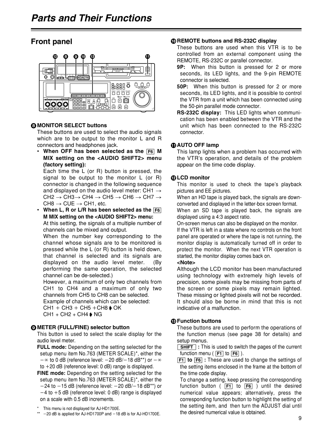
8MONITOR SELECT buttons
These buttons are used to select the audio signals which are to be output to the monitor L and R connectors and headphones jack.
•When OFF has been selected as the F6 M MIX setting on the <AUDIO SHIFT2> menu (factory setting):
Each time the L (or R) button is pressed, the signal to be output to the monitor L (or R)
connector is changed in the following sequence and displayed on the audio level meter: CH1 > CH2 > CH3> CH4 > CH5 > CH6 > CH7 > CH8 > CUE > CH1, etc.
•When L, R or L/R has been selected as the F6 M MIX setting on the <AUDIO SHIFT2> menu:
At this setting, the signals of a multiple number of channels can be mixed and output.
When the number key corresponding to the channel whose signals are to be monitored is pressed while the L (or R) button is held down, that channel is selected and its signals are displayed on the audio level meter. (By performing the same operation, the selected channel can be
However, a maximum of only two channels from CH1 to CH4 and a maximum of only two channels from CH5 to CH8 can be selected.
Example of channels which can be selected: CH1 i CH3 i CH5 iCH8 “ OK
CH1 + CH2 + CH4 “ NG
9METER (FULL/FINE) selector button
This button is used to select the scale display for the audio level meter.
FULL mode: Depending on the setting selected for the setup menu item No.763 (METER SCALE)*, either the j¶ to 0 dB (reference level: j20 dB/j18 dB**) or j¶ to i20 dB (reference level: 0 dB) range is displayed.
FINE mode: Depending on the setting selected for the setup menu item No.763 (METER SCALE)*, either the j24 to j15 dB (reference level: j20 dB/j18 dB**) or j4 to i5 dB (reference level: 0 dB) range is displayed on a scale with 0.5 dB increments.
*This menu is not displayed for
**j20 dB is applied for
:REMOTE buttons and RS-232C display
These buttons are used when this VTR is to be controlled from an external component using the REMOTE,
9P: When this button is pressed for 2 or more seconds, its LED lights, and the
50P: When this button is pressed for 2 or more seconds, its LED lights, and it is possible to control the VTR from a unit which has been connected using the
;AUTO OFF lamp
This lamp lights when a problem has occurred with the VTR’s operation, and details of the problem appear on the time code display.
<LCD monitor
This monitor is used to check the tape’s playback pictures and EE pictures.
When an HD tape is played back, the signals are down- converted and displayed in the
<Note>
Although the LCD monitor has been manufactured using technology with extremely high levels of precision, some pixels may be missing from parts of the screen or some pixels may remain lighted. These missing or lighted pixels will not be recorded. It should also be borne in mind that this is not indicative of a malfunction.
=Function buttons
These buttons are used to perform the operations of the function menus (see page 38 for details) and setup menus.
SHIFT : This is used to switch the pages of the current function menu ( F1 to F6 ).
F1 to F6 : These are used to change the settings of the setting items enclosed in the frame at the bottom of the time code display.
To change a setting, keep pressing the corresponding function button ( F1 to F6 ) until the desired numerical value appears; alternatively, press the corresponding function button to highlight the setting of the setting item, and then turn the ADJUST dial until the desired numerical value is obtained.
9