Installation Manual
Hybrid IP-PBX
Trunk Cards
Main Processing Card
MPR Option Card
Extension Cards
Cards
Power Supply Units
Optional SD Memory
PSUs
Available Proprietary Telephones
Abbreviations in this manual
Important Safety Instructions
Installation Manual
For business users in the European Union
For users in Germany only
Important Notice
For users in Finland, Norway and Sweden only
For users in New Zealand only
For users in Australia only
For Future Reference
Installation Manual
About the software version of your Hybrid IP-PBX
Structure of this Manual
About the Other Manuals
Trademarks
Precautions for Users in the United Kingdom
Installation Manual
Table of Contents
Information about the Other Cards 123
Power Failure Connections 205
Information about the Extension Cards 107
Connection of Extensions 136
215
212
Connection 213
220
Section System Outline
System Highlights
System Highlights
Hospitality Features
Portable Station PS Features
PC Phone/PC Console Features
Construction of the Basic Shelf
Basic System Construction
Basic Shelf
System Connection Diagram
Hybrid IP-PBX
DPT
Model No Model Name Description
Optional Equipment
Optional Equipment
DHLC8
PAY8
GW4E
Specifications
General Description
Extension Connection Cable
Dimension
Weight when fully
Mounted
Characteristics
System Capacity
Maximum Optional Service Cards
Cards Installed in the Slots of the Hybrid IP-PBX
LCOT4 LCOT8 LCOT16 DID8 BRI4
Card Type Maximum Number Installed KX-TDA100 KX-TDA200
MPR
BRI8 PRI23 PRI30 IP-GW4 IP-GW4E
Card Type Maximum Number Mounted on KX-TDA100 KX-TDA200
Cards Mounted on Other Optional Service Cards
Card Type Maximum Number
Maximum Terminal Equipment
APT IP-PT
Calculation Example KX-TDA100
MEC Card Calculation
MEC Card Calculation
Equipment Type MEC Figure
PSU Capacity
Power Supply Unit Selection
Load Figure Calculation
Equipment Type Load Figure
Calculation Example KX-TDA200
Specifications
Section Installation
Safety Installation Instructions
Before Installation
Before Installation
Installation Precautions
Before Installation
KX-TDA100 KX-TDA200
Installation of the Hybrid IP-PBX
Unpacking
Names and Locations
Inside View
Opening/Closing the Front Cover
Opening the Front Cover
Closing the Front Cover
Safety Instructions
Installing/Replacing the Power Supply Unit
Accessories and User-supplied Items
Accessories included Screws ×
Installing the Power Supply Unit
Replacing the Power Supply Unit
Replace the PSU
Frame Earth Connection
Connect the frame of the Hybrid IP-PBX to earth
User-supplied Items
Backup Battery Connection
Backup Power Supply Duration
Examples
Connecting Backup Batteries
Installing/Removing the Optional Service Cards
Installing Optional Service Cards
Back Board Release Lever
Covering the Blank Slots
Handling of the Cables
Removing the Optional Service Cards
CTI-LINK KX-TDA0410
Types of Connectors
Connector Type Pin Number Used for
BNC
MPR USB
Attaching a Ferrite Core
When connecting a T1/E1/PRI/IP-GW16/IP-EXT16 card
When connecting a BRI card
When connecting an extension card
Fastening Amphenol Connector
Amphenol Connector Pin Assignment Chart
LCOT4 LCOT8 LCOT16 DID8 DHLC8 DLC8 DLC16 MSLC16 SLC8
Wall Mounting KX-TDA200
Installation of the Hybrid IP-PBX
Wall Mounting KX-TDA100
Wall
Installation of the Hybrid IP-PBX
Floor Standing KX-TDA200 Only
TOP Front
Overview
Surge Protector Installation
Installation
IP-PBX SLT PT
IP-PBX
Outside Installation
Installation of an Earth Rod
Installation of the Hybrid IP-PBX
USB BGM/MOH
Information about the Main Processing Card
MPR Card
LED Indications
Batt Alarm
SD Access
Indication Colour Description
MEC Card KX-TDA0105
RMT Card KX-TDA0196
Information about the Trunk Cards
LED
Pin Assignments
Amphenol Connector
Signal Name Function
Card Status
2 DID8 Card KX-TDA0182
LED Indications
3 CID/PAY8 Card KX-TDA0189
Switch Settings on LCOT8/LCOT16 cards
Switch Type Usage and Status Definition
DIP
4 CID8 Card KX-TDA0193
5 E&M8 Card KX-TDA0184
SGA
T1A
R1A
SGB
LED Indications
Switch Settings
6 T1 Card KX-TDA0187
Signal Name Level Function
RJ45 Connector for Trunk Use
RJ45 Connector for Extension Use
Maximum Cabling Distance of Extension Connection
Sync
BNC RX
7 E1 Card KX-TDA0188
BNC TX
BNC coaxial Connector TX
BNC coaxial Connector RX
8 BRI4 Card KX-TDA0284 and BRI8 Card KX-TDA0288
RX1
TX1
RX2
TX2
Master Clock LED Pattern
Line LED Pattern
Line
OFF
Maximum Cabling Distance of S0 Bus Connection
9 PRI30 Card KX-TDA0290CE/CJ
Switch Settings
Link
Maximum Cabling Distance of Extension Connection
10 PRI23 Card KX-TDA0290
Pin Assignments
Maximum Cabling Distance of Extension Connection
IP-GW4 Card KX-TDA0480
RJ45 Connector 10BASE-T
Signal Name Input I/Output O Function
IAM Busy
Alarm
Online
Data
RJ45 Connector 10BASE-T/100BASE-TX
IP-GW4E Card KX-TDA0484
OFF
IP-GW16 Card KX-TDA0490
LED Indications
Information about the Extension Cards
CSIF4 Card KX-TDA0143 and CSIF8 Card KX-TDA0144
Powl
RJ45 Connector
Powh
DHLC8 Card KX-TDA0170
D2B
D2A
D1A
D1B
LED Indications
3 DLC8 Card KX-TDA0171
Data port 1 Low
4 DLC16 Card KX-TDA0172
D2J
D2I
D1I
D1J
5 SLC8 Card KX-TDA0173
Pin Assignments
EXT-CID Card KX-TDA0168
7 SLC16 Card KX-TDA0174 and MSLC16 Card KX- TDA0175
Ring port Tip port 17-25 Reserved 42-50
IP-EXT16 Card KX-TDA0470
Online
1 OPB3 Card KX-TDA0190
Accessories included none User-supplied not included none
Information about the Other Cards
User-supplied not included Copper wire
2 DPH4 Card KX-TDA0161
DP3
Pin Terminal Block
DP4
DP2
3 DPH2 Card KX-TDA0162
Pin Assignments
Path Doorphone Call Path
4 EIO4 Card KX-TDA0164
Pin Assignments
External Relay
Connection Diagram
External Sensor
ECHO16 Card KX-TDA0166
6 MSG4 Card KX-TDA0191
CTI-LINK Card KX-TDA0410
Link Status
DSS Console
Connection of Extensions
PT-interface CS
With APT
Using a Modular T-Adaptor
Parallel Connection of the Extensions
With DPT
Dptslt
Using an EXtra Device Port
With KX-T7600 Series DPT except KX-T7665
With Other DPT except KX-T7560 and KX-T7565
Back View of DPTs
Digital EXtra Device Port Digital XDP Connection
With KX-T7600 Series DPT except KX-T7600E Series
To TEL To Main Unit
With KX-T7600E Series DPT
Connecting to a Slave DPT
Connecting to a Master DPT
First Party Call Control CTI Connection
Overview
RF Specification
Connection of Dect Portable Stations
CS Cell Station KX-TDA0142CE/KX-TDA0141CE
Equipment Distance
Prepare for site survey
Procedure Overview
Investigate the installation site
Conduct the site survey
Finish the site survey
Mount the CS on the wall
Understanding Radio Waves
Characteristics of Radio Waves
Site Planning
Object Material Transmission Tendency
Site Survey Preparation
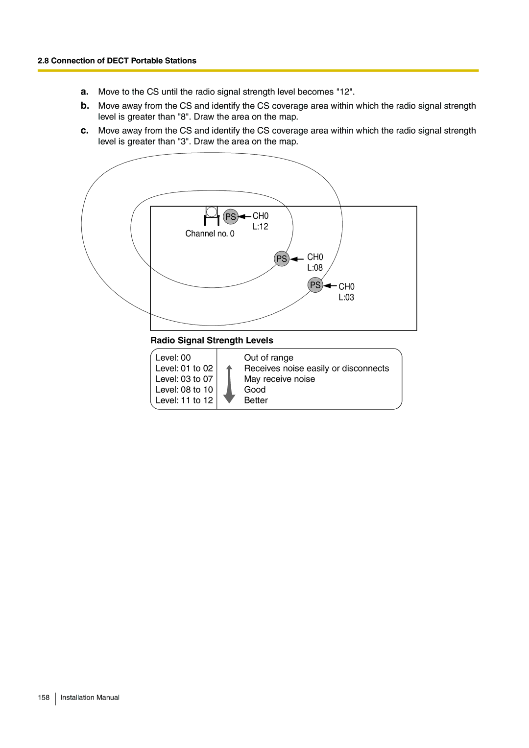
Radio Signal Strength Levels
CS Coverage Area
Things to take note
Example Installing in a Room Separated by Interior Walls
CS installation plan
Assigning the CS ID Number to the PS
Before Site Survey
Checking the CS ID Number
CS No
Using the KX-TD7590 To enter letters
Setting and Installing the CS Temporarily for Site Survey
DIP Switch
For users in the United Kingdom
Site Survey Using the KX-TCA255/KX-TD7590
Testing the Radio Signal Strength
PS CH0
Channel no
Clearing the Stored Scan Data
Using the KX-TD7590 Log No
Referring to the Stored Scan Data
After Site Survey
Accessories and User-supplied Items for the CS
Connecting a Cell Station to the Hybrid IP-PBX
Using a Csif Card
User-supplied not included RJ11 connector
Using a DHLC/DLC Card
Connecting the CS
For the KX-TDA0142CE User only
Registering the PS
Administrator Level
Using the KX-TCA155/KX-TCA255
PS Registration
Using the KX-TD7580
System Lock Password
System Lock Password /OK
Setting the PIN for Hybrid IP-PBX
Changing the Display Language of the PS
Handset PIN
691
PS Termination
Testing the Operation
Wall Mounting
Install a screw here 71 mm
Reference for Wall Mounting
Connection of 2.4 GHz Portable Stations
KX-TDA0142 Using a Csif Card
KX-TDA0141 Using a DHLC/DLC Card
CS Cell Station KX-TDA0142/KX-TDA0141
Connection of 2.4 GHz Portable Stations
Prepare the CS for site survey
Using the KX-TD7680
Using the KX-TD7690
Finish the site survey
Site Planning
Object Material Transmission Tendency
CS Coverage Area
Example Installing in a Room Separated by Interior Walls
CS Number Switch Radio Signal Test Switch CS no CS no CS no
Connection of 2.4 GHz Portable Stations
Site Survey
Scan Data No
PS CS NO.1 LEVEL12
Scan Data No
Deleting the Stored Scan Data
After Site Survey
Connecting a Cell Station to the Hybrid IP-PBX
Using a DHLC/DLC Card
Connecting the CS
PS Using the KX-TD7680
Entering the System Programming Mode
PT Administrator Level
System Setting Menu
When the PS has not been registered yet
Setting the System Lock
Setting the PIN for PS Using the KX-TD7680
692
System
Wall Mounting
Reference for Wall Mounting
Installing the Doorphone KX-T30865
Maximum Cabling Distance
Connection
Installation Manual
BGM
Connection of Peripherals
Connection of Peripherals
PC/Printer via RS-232C
Connection Charts
Pager
Pin Assignments
Signal Ground SG
For connecting a printer/PC with a 25-pin RS-232C connector
RS-232C Signals
Receive Data RXD…input
USB D
PC/CTI Server via USB version
Vbus
USB D+
Using Analogue Trunk Card and Extension Card
Power Failure Connections
Power Failure Connections
PFT Ports 1 Signal Name Function
RJ11 Connector Pin Assignments for Analogue Trunk Card
RJ11 Connector Pin Assignments for Extension Card
PFT Ports 3 and 4 for LCOT16 card only Signal Name Function
RJ45 Connector Line 1 Pin Assignments
Using BRI Card
Switch Settings
RJ45 Connector Line 2 Pin Assignments
Starting the Hybrid IP-PBX
Starting the Hybrid IP-PBX
Confirming the Trunk Connection
RUN
Section Guide for the KX-TDA Maintenance Console
KX-TDA Maintenance Console*1
Overview
Serial Interface Connection
Connection
Connection
LAN Connection via CTI-LINK Card
External Modem Connection
SD TXD RD RXD DR DSR ER DTR
Password Security
Installation of the KX-TDA Maintenance Console
Installing and Starting the KX-TDA Maintenance Console
System Requirements
Installing the KX-TDA Maintenance Console
Start the KX-TDA Maintenance Console from the Start menu
When country/area data do not match
Installation of the KX-TDA Maintenance Console
Section Troubleshooting
Troubleshooting
Installation
Problem Probable Cause Solution
Cause
Trunk is connected to the T2/R1
Operation
Problem Probable Cause Solution
Using the Reset Button
Operation
Description
Troubleshooting by Error Log
Error Log Display Format
Description
SLC, CSIF, LCOT, T1, E1
List of Errors and Solutions
Error Code Error Message
BRI, PRI, OPB3, E&M, IP
System Start-up and On-line Operation
Probable Cause Solution
Probable Cause Solution
OPB3, CTI-LINK, E&M
ROM NG
CSIF, T1, E1, BRI, PRI
RAM NG IP-GW, DID, SLC8, IP
MPR-LPR CSIF, T1, E1, BRI, PRI
IP-GW Sdram
IP-GW Dpram
IP-PT SUB-CPU
Probable Cause Solution
Probable Cause Solution
Section Appendix
Revision History
New Contents
Changed Contents
Pmpr Software File Version
Pmpr Software File Version
Pmpr Software File Version
Index
Numerics
PSU
PSU-L PSU-M PSU-S
Index
62, 4-chome, Minoshima, Hakata-ku, Fukuoka 812-8531, Japan