●Unit Version
The unit ID is defined by the upper 3 bits depending on the software version installed in the unit.
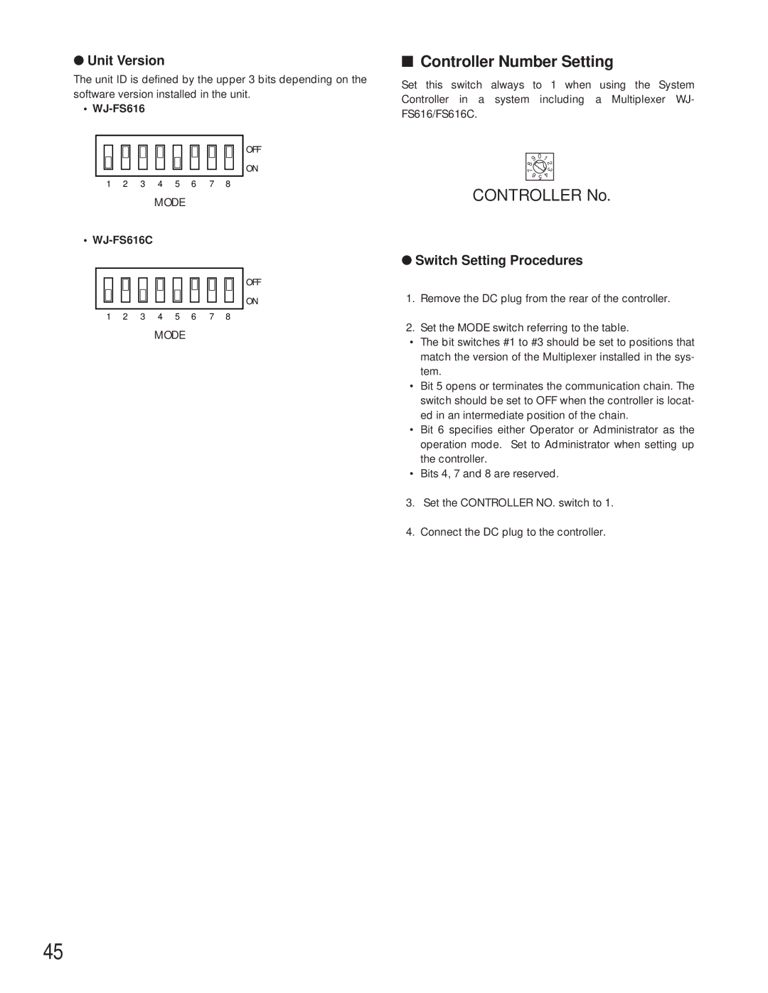
• WJ-FS616
OFF
ON
1 2 3 4 5 6 7 8
MODE
• WJ-FS616C
OFF
ON
1 2 3 4 5 6 7 8
MODE
■Controller Number Setting
Set this switch always to 1 when using the System Controller in a system including a Multiplexer WJ- FS616/FS616C.
9 | 0 | 1 |
8 |
| 2 |
|
| |
7 |
| 3 |
6 | 5 | 4 |
|
CONTROLLER No.
●Switch Setting Procedures
1.Remove the DC plug from the rear of the controller.
2.Set the MODE switch referring to the table.
•The bit switches #1 to #3 should be set to positions that match the version of the Multiplexer installed in the sys- tem.
•Bit 5 opens or terminates the communication chain. The switch should be set to OFF when the controller is locat- ed in an intermediate position of the chain.
•Bit 6 specifies either Operator or Administrator as the operation mode. Set to Administrator when setting up the controller.
•Bits 4, 7 and 8 are reserved.
3.Set the CONTROLLER NO. switch to 1.
4.Connect the DC plug to the controller.
45