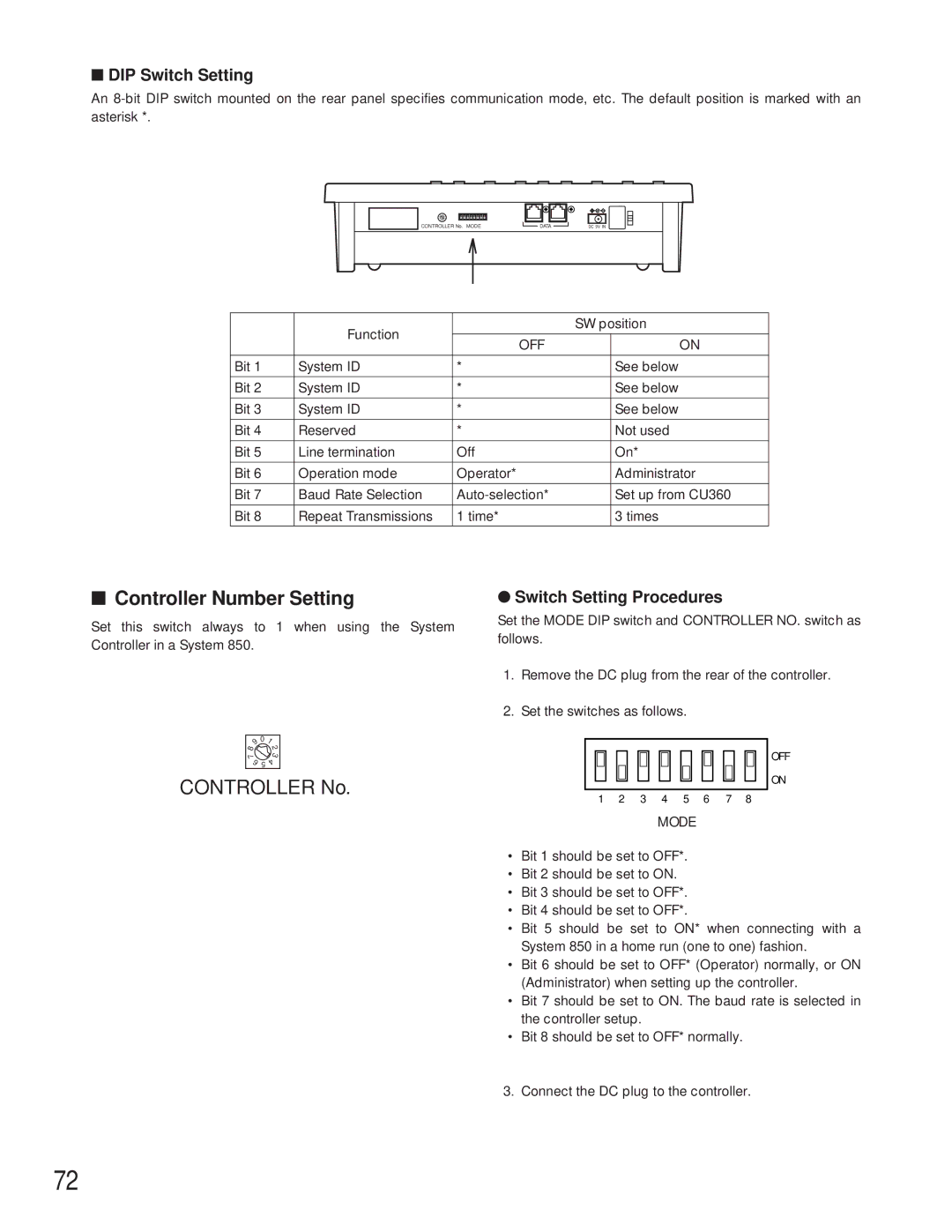
■DIP Switch Setting
An
0 | 12 |
78 | 3 |
65 |
|
CONTROLLER No. MODE
DATA | DC 9V IN |
| Function |
| SW position | |
|
|
|
| |
| OFF |
| ON | |
|
|
| ||
|
|
|
|
|
Bit 1 | System ID | * |
| See below |
|
|
|
|
|
Bit 2 | System ID | * |
| See below |
|
|
|
|
|
Bit 3 | System ID | * |
| See below |
|
|
|
|
|
Bit 4 | Reserved | * |
| Not used |
|
|
|
|
|
Bit 5 | Line termination | Off |
| On* |
|
|
|
|
|
Bit 6 | Operation mode | Operator* |
| Administrator |
|
|
|
|
|
Bit 7 | Baud Rate Selection |
| Set up from CU360 | |
|
|
|
|
|
Bit 8 | Repeat Transmissions | 1 time* |
| 3 times |
|
|
|
|
|
■Controller Number Setting
Set this switch always to 1 when using the System Controller in a System 850.
9 | 0 | 1 |
8 |
| 2 |
|
| |
7 |
| 3 |
6 | 5 | 4 |
|
CONTROLLER No.
●Switch Setting Procedures
Set the MODE DIP switch and CONTROLLER NO. switch as follows.
1.Remove the DC plug from the rear of the controller.
2.Set the switches as follows.
OFF
ON
1 2 3 4 5 6 7 8
MODE
•Bit 1 should be set to OFF*.
•Bit 2 should be set to ON.
•Bit 3 should be set to OFF*.
•Bit 4 should be set to OFF*.
•Bit 5 should be set to ON* when connecting with a System 850 in a home run (one to one) fashion.
•Bit 6 should be set to OFF* (Operator) normally, or ON (Administrator) when setting up the controller.
•Bit 7 should be set to ON. The baud rate is selected in the controller setup.
•Bit 8 should be set to OFF* normally.
3. Connect the DC plug to the controller.
72