OnSite 2800 Series User Manual | 2 • Hardware installation |
|
|
The signal
Table 7. Signal
Pin | Signal | Pin | Signal |
|
|
|
|
1 | Frame Ground | 8 | Signal Ground |
2 | TXDa | 9 | TXDb |
|
|
|
|
3 | CNTa | 10 | CNTb |
4 | RXDa | 11 | RXDb |
|
|
|
|
5 | INDa | 12 | INDb |
6 | SETa | 13 | SETb |
|
|
|
|
The the router’s X.21 interface is wired as a DCE. No DTE configuration is possible. The router’s X.21 inter- face requires a cable with a male
Installing the T1/E1 twisted pair cables. The PRI is usually connected to a PBX or switch (local exchange (LE)). Type and
Table 8.
Pin | Signal |
|
|
1 | TX tip |
2 | TX ring |
|
|
3 | TX shield |
4 | RX tip |
|
|
5 | RX ring |
6 | RX shield |
|
|
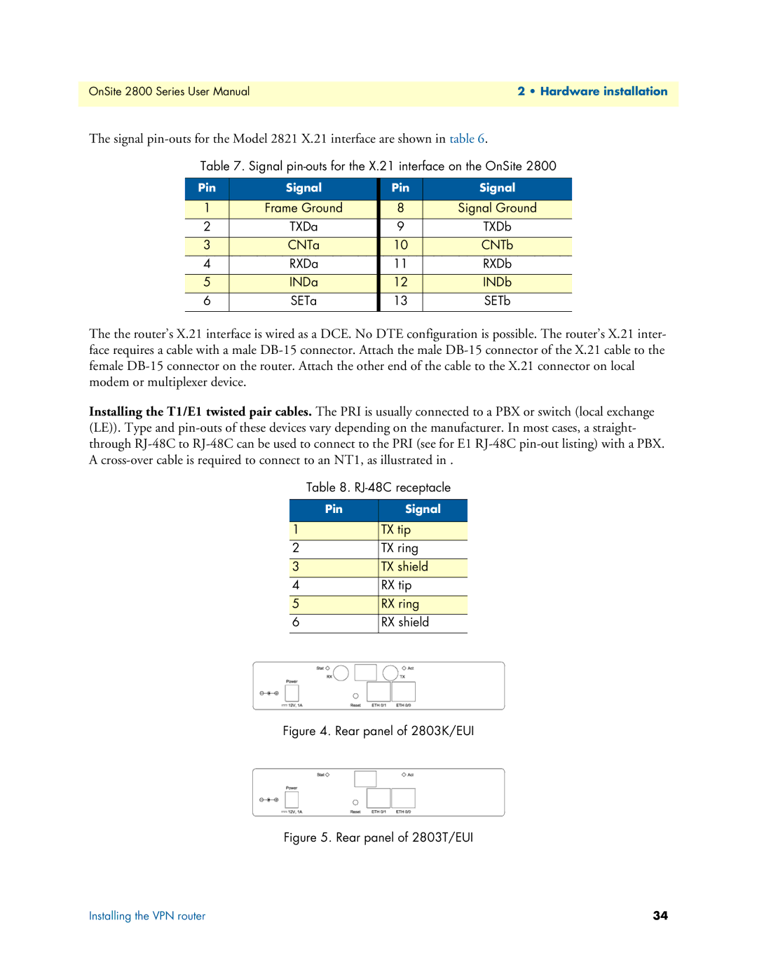
Figure 4. Rear panel of 2803K/EUI
Figure 5. Rear panel of 2803T/EUI
Installing the VPN router | 34 |