Patton electronic 2800 user manual Hardware installation

Models: 2800

1 135
Download 135 pages 34.01 Kb
Page 33
Image 33

OnSite 2800 Series User Manual

2 • Hardware installation


The router’s V.35 interface is wired as a DTE. No DCE configuration is possible. If you are directly connect- ing the router’s V.35 interface to third-party equipment that cannot be configured as a DCE, you must use a tail-circuit cable. You can purchase a tail-circuit cable from a datacom-supply vendor. A tail-circuit cable will cross-over the necessary V.35 signals so that the two DTE interfaces can communicate.

Note Some third-party equipment will not be able to work properly in DTE-to-DTE configurations even when using a tail-circuit cable. Please refer to your third party equipment user manual for informa- tion on DTE-to DTE operation.

The router’s V.35 interface requires a cable with a male DB-25 connector. Attach the male DB-25/M35 con- nector of the V.35 cable to the female DB-25 connector on the router. Attach the other end of the cable to the V.35 connector on local V.35 modem or multiplexer device.

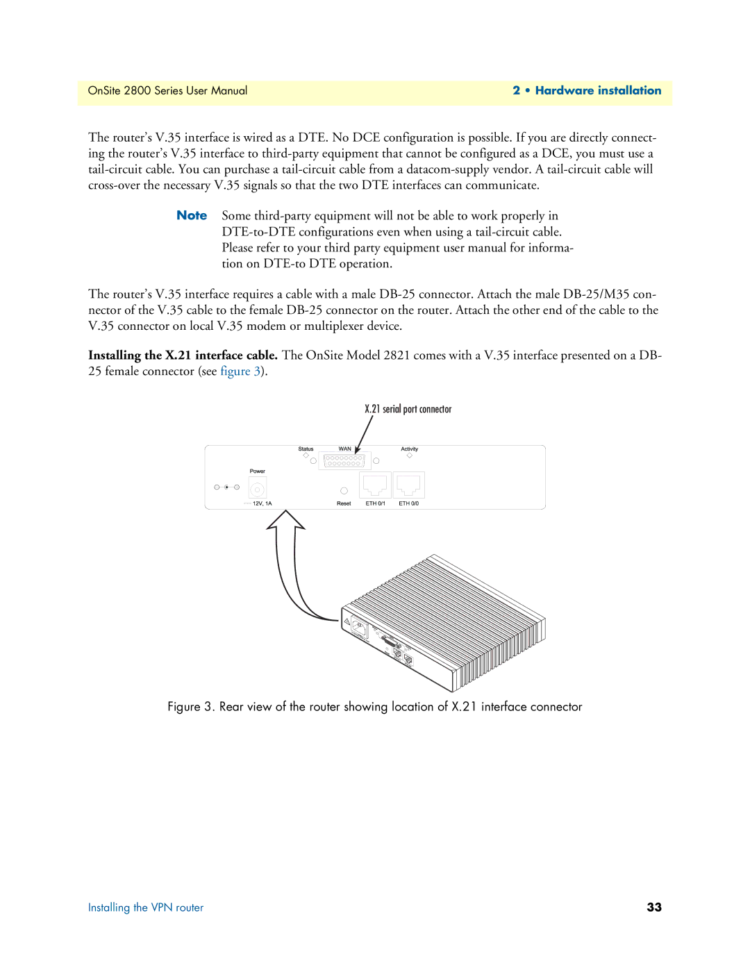
Installing the X.21 interface cable. The OnSite Model 2821 comes with a V.35 interface presented on a DB- 25 female connector (see figure 3).

X.21 serial port connector

Figure 3. Rear view of the router showing location of X.21 interface connector

Installing the VPN router

33

Page 33
Image 33
Patton electronic 2800 user manual Hardware installation