LQH-HW
Page
LineJet Printers
Copyright 2000, HEWLETT-PACKARD CO
Trademark Acknowledgements
Page
Table of Contents
Table of Contents
Bar Codes
Standard Ascii Character Set
Vertical Paper Motion
Table of Contents
IGP/PGL Emulation
Features
About this Manual
IGP/PGL Emulation
How the IGP Operates
Modes of Operation
Modes of Operation
Quiet Mode
Normal Mode
Modes of Operation Normal Mode Commands Mnemonic Description
IGP/PGL Emulation Normal Mode Commands Mnemonic Description
Create Form Mode
Create Logo Mode
BOX
Execute Form Mode
Sfoff Sfcc
Alphanumeric Data
Semicolon
IGP Command Standards
Inline Commands
Special Function Control Code Sfcc
Spaces
Command Parameters
Line Terminator
Printable Character
Storing Data
Comments in Command Lines
Prompt
Numeric Values
CP.DP Format Example
Character Position.Dot Position CP.DP Format
Data Fields for Alphanumeric and Incremental Data
Command Codes
Dark Printing
Command Codes
Mode
Alphanumerics
Alphanumerics
Purpose
Dark
DIR
Defines the vertical expansion factor to enlarge
Command enter STOP, and the IGP will wait for a
New command. If not entered, the IGP will wait for
Another set of Alphanumeric command parameters
Stop
Alphanumeric Example
Alphanumerics, Incremental Fields
Using Incremental Alphanumeric Data
Character Type and Function
Alphanumerics, Incremental Fields
Increment Alphanumeric
Printed Results ABC123
Command Codes Value Description
Printed Results
Printed Results 1ABC123
Printed Results 42AR
Alphanumerics, Incremental Fields Value
Printed Results Description
Printed Results AA98
RPT n
Alphanumerics, Incremental Fixed Data Fields
Format Alpha
Alphanumerics, Incremental Fixed Data Fields
Cn IAFnL DIR UC Dark Point HSn or HSDnSR SC VE HE Stop
Alphanumerics, Incremental Dynamic Data Fields
Field B
Alphanumerics, Incremental Dynamic Data Fields
Field a
Where
Stop BOX
Boxes
Boxes
BOX
Box Example
Compressed Print Density
Compressed Print Density
END
Configuration
Config
Parametervalue
Configuration Configuration Parameters Value
END
Stop Corner
Corners
Corners
Corner
Corner Example
Create
Create
Delete Form
Flash memory where it was originally stored. Enter
Delete Form
Disk
Delete Logo
Memory where it was originally stored. Enter Disk
Delete Logo
Directory
Dup#
Duplication, Horizontal
Format Hdup dup# offset# elements to be duplicated
Hdupoff
Vert
Duplication, Horizontal
Vdupoff
Duplication, Vertical
Vdup dup# offset#
Elements to be duplicated
Format END
Emulation Switching
Emulation Switching
End
Print Formats in the Execute Form Mode
Execute Form Mode
How to Use the Execute Command
Execute
Execute Form General Format
Execute Form General Format
Form Feed character ccNORMAL
Form Feed Character
CcAFnDASCII textD
CcBFn DdataD
CcGFnDlogonameD
Execute Form Electronic Vertical Format Unit
Execute Form Electronic Vertical Format Unit
Format ccAFn Dascii textD
Execute Form Dynamic Alphanumeric Data
Format ccBFn Ddata fieldD
Execute Form Dynamic Bar Code Data
Execute Form Dynamic Bar Code Data
Format ccGFnDlogonameD
Execute Form Dynamic Logo
Form1 Form2 Form3 Form4 Form5 Form6 = ICNT6
Execute Form Incremental Dynamic Data
Execute Form Incremental Dynamic Data
Format ccEXECUTE formname page n FC ICNTn IRSTn
IAF
Supplying Dynamic Data for Incremental Fields
CcIAFn idir Stepmask RPTn RSTn Dstartdatad
CcIBFn idir Stepmask RPTn RSTn Dstartdatad
Execute Form Overlay Data
Execute Form Overlay Data
Expand
Expanded Print
Font
Font
Font
LFORM8
Form Length
LFORM6
Ignore Sequence
Ignore Sequence
Line Spacing
Format Horz
Lines, Horizontal
Format Vert
Lines, Vertical
Lines, Vertical
SR SC logoname Disk
Listen
Logo Call
Format Logo
Logo Call
Dot
Logo Mode, Create
Logoname
Row#
Logo Mode, Create
SR SC
Normal Mode
Number
Paper
Paper
Paper Instruction Data Bit
DIS-PI
Paper Instruction PI Enable/Disable
Print File
EN-PI
Quiet
Quiet
Recall
Quiet
Reverse
Reset
Reset
Reverse Print
Lpi
Scale
Scale
Horz/vert
Sfoff
Command Paper Movement Function
Select Format
Sfon
Setup
Setup
Setup
Host Data ccSETUPEND
Format ccSFCC n or ccSFCC ‘n’
Special Function Control Code Change
Overview
Bar Codes
Available Bar Codes Mnemonic Symbol Code Set Length
User-Defined Variable Bar Code Ratios
User-Defined Variable Bar Code Ratios
Variable Ratio Sample
Density cpi
UPC and EAN
Other Bar Codes
Ratio
Codabar
Bar Codes
Codabar
Data Field
Codabar Command Format
Quiet Zone
Start/Stop Codes
Optional parameter to adjust the overall height
Expand the bar code symbol. The magnification
Default value is X1. As required for scanning, enter
Magnification. Increasing the magnification adjusts
Stop is not entered, an error message results
Is specified based on the Scale command
Printable data field. The default value is B, locating
Ends the Bar Code command while the IGP/PGL
Codabar Codabar Character Set Hex
Codabar Example
Code 39 Structure
Code
Code
Stop Barcode
Code 39 Command Format
Locates the printable data field above the bar code
NUL
Code 39 Character Set
Sample Code 39 Bar Codes
Code 39 Example
Code 93 Structure
Quiet Zone
Code 93 Command Format
Allowed if a null data field was specified
Sfcc
Start Stop
Code 93 Example
Code 128 Structure
Code 128A, 128B and 128C
Code 128A, 128B and 128C
Code 128A Data Field
Code 128B Data Field
Code 128C Data Field
Code 128 Command Format
Replace n with a number ranging from 1 to
Optional parameter to enable printing of the human
Code 128A, 128B and 128C Code 128A Character Set Hex
Code 128B Character Set Hex
See Note
Code 128A, 128B and 128C Code 128C Character Set Hex
Sample Code 128B Bar Codes
Code 128B Example
Sample Code 128C Bar Codes
Code 128C Example
EAN
Start/Center/Stop Codes
SCB
EAN 8 Command Format
Length of the data field need not be
EAN 8 Example
EAN
EAN
Number System Character
EAN 13 Command Format
Add-on data
127
Sample EAN 13 Bar Codes
EAN 13 Example
FIM
Guide to Business Mail Preparation
FIM Structure Vscan or CCW
Start/Stop Code
FIM Command Format
Clear Zone
Value 1/8-inch from the top edge of the mail piece
Sample Fimb Bar Code
FIM Example
Sample Fimc Bar Code
Interleaved 2/5 I-2/5, German I-2/5 and ITF-14
Interleaved 2/5 I-2/5, German I-2/5 and ITF-14
Quiet Zone
5 Command Format
Parameter to enter data when the BFnL
Height of the bar code body is reduced 0.1-inch
Sample I-2/5 Bar Codes
5 Example
Matrix
Matrix
Quiet Zone
Default value is 0.9-inch
Matrix Command Format
Dark
Readable data is not printed. This parameter is not
Sample Matrix Bar Codes
Matrix Example
MSI
Quiet Zone
MSI Command Format
BFnL
151
Sample MSI Bar Codes
MSI Example
Quiet SR, SC Zone Position Stop Code
Security Level
Ddata fieldD
Optional parameter that specifies the security level
157
Postnet
Postnet
Quiet Zone
Postnet Command Format
Mail piece. Character column or dot column is
Stop is not entered, an error message will result
Postnet Example
Value within the 1/2-inch left and right margins
PostBar and Royal Mail KIX
PostBar and Royal Mail KIX
KIX Format
KIX
PostBar and Royal Mail Command Format
Defines the starting column of the bar code
On the Scale command page 83, or use
Defines the starting row for the bar code. Character
Row or dot row is specified based on the Scale
Sample Royal Mail bar code X1A Magnification
PostBar and Royal Mail Examples
Telepen
Telepen
Quiet Zone
Data field D
Telepen Command Format
89, or use the CP.DP format
Telepen Character Set
Sample Telepen Bar Code
Telepen Example
UCC/EAN-128
174
175
176
Quiet Zone
Modulo-10 Data Field Check Digit for SSCC-18 and SCC-14
Modulo-103 Check Digit
Code UCC-128 Command Format
Replace L with the maximum number
Start code and subset switching is done
~CREATEUCCTEST
Code UCC/EAN-128 Examples
183
184
UPC-A
Quiet Zone
UPC-A Command Format
Specified, since it is fixed at 11 digits, plus any
Is specified in the Font parameter. UPC-A human
Sample UPC-A Bar Codes with Add-On Data
UPC-A Example
UPC-E and UPC-E0
UPC-E and UPC-E0
Quiet Zone
UPC-E or UPC-E0
UPC-E Command Format
Type
Specified, since it is fixed at 6 or 11 digits, plus
Is specified in the Font parameter. UPC-E data
Eleven-Digit Compression
Sample UPC-E Bar Code
UPC-E Example
Upcship
Upcship
Upcship Command Format
201
Sample Upcship Bar Codes
Upcship Example
UPS
UPS
UPS 11 Command Format
BFnL
206
Sample UPS 11 Bar Code
UPS 11 Example
Incremental Bar Code Fields
Incremental Bar Code Fields
Incrementing Bar Code Data
Stepmask Startdata
Incrementing Bar Code Data Incremental Bar Code Data
Incremental Bar Code Fields Value Description
RST n
Incremental Bar Code Fixed Data Fields
Incremental Bar Code Fixed Data Fields
Type Vscan MAG Hn I Dark SR SC
Incremental Bar Code Dynamic Data Fields
Barcode Stop
Incremental Bar Code Dynamic Data Fields
Duplicating Incremental Bar Code Fields
Example Basic Create Form
Form Examples
Form Examples
Basic Create Form Example
Example Basic Create Form
Basic Design
Example Dynamic Data
Sample Form
Example Dynamic Data
Bar Code Fields
Dynamic Alphanumeric Fields
Dynamic Alphanumeric and Bar Code Data
~NORMAL
Dynamic Data Example
50.8722 C1554.5400*ACME MOTOR, INC Irvine CA 92713 714
Example Auto Increment Fields
226
Auto Increment Fields Example
Creating a Box and Corners
Form Exercise
Stop END
Creating a Box and Corners
Box and Corner Example
Adding Horizontal and Vertical Lines
SRSCVEHEDTextD
Adding Fixed Alphanumeric Text
Adding Fixed Alphanumeric Text
232
Enter
Adding a Bar Code
Adding a Bar Code
RECnAFnLDIRUCSRSCVEHEDTextD Stop previously input
Completed Practice Form Example
Logo Exercise
Logo Exercise
SRSClogoname
Creating a Logo
Creating a Logo
CcLOGOlogonameVLHL
238
Layout Considerations
Form Design
Layout Considerations
Planning the Form Layout
Form Design
Sample Form Design
Planning the Form Layout
Logo Design
VDUPdup#offset#
Creating a Form and Adding Form Components
Creating a Form and Adding Form Components
~CREATEHCBOATS
DdatafieldD
RECnAFnLDIRUCDARKSRSCVEHEDtextD
Dark Srsc
Print HNDCFT.FOM
Logo 1218HANDCRFT
Completed Sample Form
~DIRECTORY
Directory Command
Example
DIRECT.FOM
Delete Command
Delete Command
Solving Program Errors
Sfcc Create /PRACTICE BOX
Solving Program Errors
Multinational Character Sets and Set Values
Introduction
Supported Character Sets
Substitution Set Hex Values
Character Addresses
Making Character Substitutions
Introduction
Data Bit
Accessing Characters and Character Sets
Power-Up Character Set Selection
OCR Character Sets
Accessing Characters and Character Sets
User-Defined Set Command Uset
Iset n
User-Defined Set Command Uset USET-ISET Relationship Uset n
Iset
Character Set Selection Command Iset
Multinational Character Sets
Multinational Character Sets
Swedish Set Norwegian Set Danish Set Finnish Set 258
English Set French Set Dutch Set Spanish Set 259
Italian Set Turkish Set OCR-A Set OCR-B Set 260
IGP/PGL Emulation Error Codes
Error Codes
Horizontal Line Errors
Vertical Line Errors
Box Errors
Corner Errors
Alpha Errors
Logo Errors
Create Errors
Execute Errors
Miscellaneous Errors
Bar code type is not supported
Bar Code Errors
ALPHA/BARCODE syntax error
Missing or wrong delimiter must be a colon
Dynamic Barcode symbol exceeds the form width
Barcode symbols exceeds the form length
Barcode symbols exceeds the form width
Dynamic Barcode symbol exceeds the form length
Dynamic ALPHA/BARCODE field longer than previously defined
Reverse Print Errors
Sfcc decimal input error must be 1
Execute form too wide for current page setting
Multinational Character Set Errors
Incremental Fields Errors
Multinational Character Set Errors
276
Standard Ascii Character Set
Appendix a
Grid Programs Samples
Page
Page
Page
Paper Motion Using the PI Line Relative Line Slewing
Paper Motion Using Line Feeds and Form Feeds
DLE DC1 DC2 DC3 DC4 NAK SYN ETB Can
Configuration Value
Line Space Slewing Data Bits Slew Range
Hex Dec Code
General Evfu Programming
Paper Motion Using the Evfu
General Evfu Programming
Evfu Programming Sequence
Channel Assignment
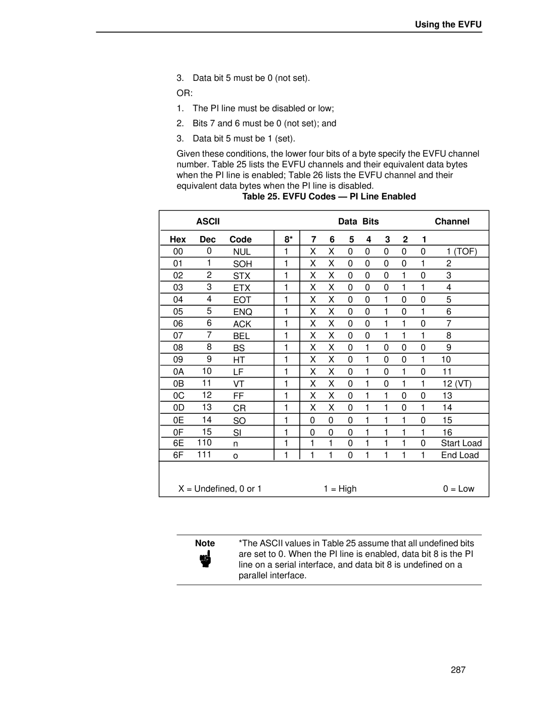
Using the Evfu
Appendix C Paper Motion Using the Evfu
Start Load Code 1E or 6E Hex
SOH STX ETX EOT ENQ ACK BEL
Using the Evfu
Evfu Codes PI Line Enabled
Data Bits Channel Hex Dec Code
Evfu
Clearing the Evfu Memory
DC1 DC2 DC3 DC4 NAK SYN ETB Can SUB ESC
Evfu Example
Evfu Format in Execute Mode
Evfu Example
Assign Line Identification Codes
1BDATA for Vertical TAB Channel 15DATA for Line
Top of form, Form #2
Evfu Example Evfu Channel Code Sent Line No Form Output
Top of form, Form #1
Undefined hex 17 causes single line feed
292
Index
Page
Page
Page
IGP
Postnet
UCC/EAN-128
300
Page
Manual Part Number 171250-001PX