3 – FVIC Configuration and Monitoring Features Fibre Channel Configuration
Q
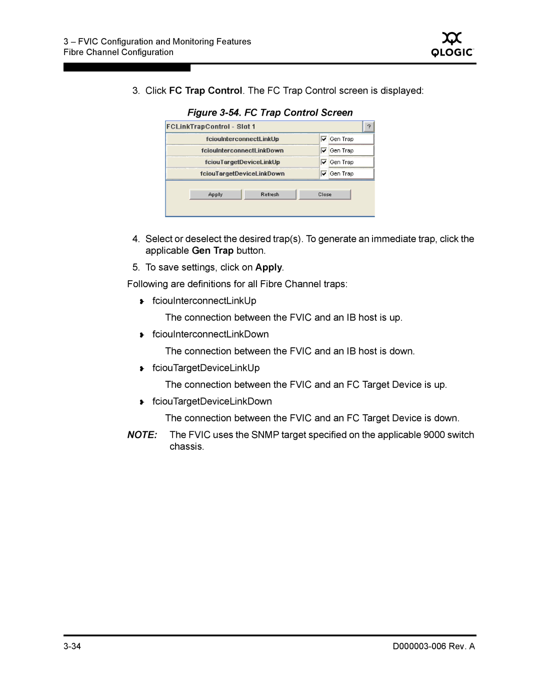
3.Click FC Trap Control. The FC Trap Control screen is displayed:
Figure 3-54. FC Trap Control Screen
4.Select or deselect the desired trap(s). To generate an immediate trap, click the applicable Gen Trap button.
5.To save settings, click on Apply.
Following are definitions for all Fibre Channel traps:
❥fciouInterconnectLinkUp
The connection between the FVIC and an IB host is up.
❥fciouInterconnectLinkDown
The connection between the FVIC and an IB host is down.
❥fciouTargetDeviceLinkUp
The connection between the FVIC and an FC Target Device is up.
❥fciouTargetDeviceLinkDown
The connection between the FVIC and an FC Target Device is down.
NOTE: The FVIC uses the SNMP target specified on the applicable 9000 switch chassis.
|