Q
2 – Operations and Administration
Additionally, the Component Information Area has Apply and Refresh buttons, which perform the following functionality:
Apply:
Saves any user edits within the white fields to flash memory. Refresh:
Refreshes all fields in the information areas.
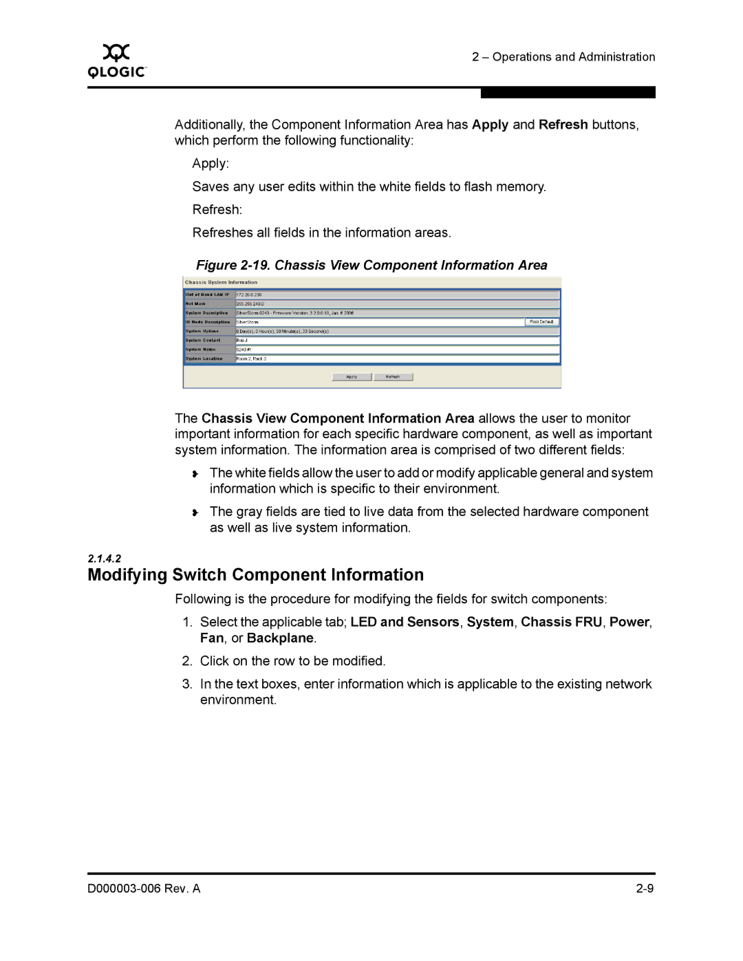
Figure 2-19. Chassis View Component Information Area
The Chassis View Component Information Area allows the user to monitor important information for each specific hardware component, as well as important system information. The information area is comprised of two different fields:
❥The white fields allow the user to add or modify applicable general and system information which is specific to their environment.
❥The gray fields are tied to live data from the selected hardware component as well as live system information.
2.1.4.2
Modifying Switch Component Information
Following is the procedure for modifying the fields for switch components:
1.Select the applicable tab; LED and Sensors, System, Chassis FRU, Power, Fan, or Backplane.
2.Click on the row to be modified.
3.In the text boxes, enter information which is applicable to the existing network environment.