Proceed as follows to connect the CinemaWall to your video sources, external controller(s)
– if present – and AC power.
When connecting your equipment:
•Turn off all equipment before making any connections.
•Use the correct signal cables for each source.
•Ensure that the cables are securely connected. Tighten the thumbscrews on connectors that have them.
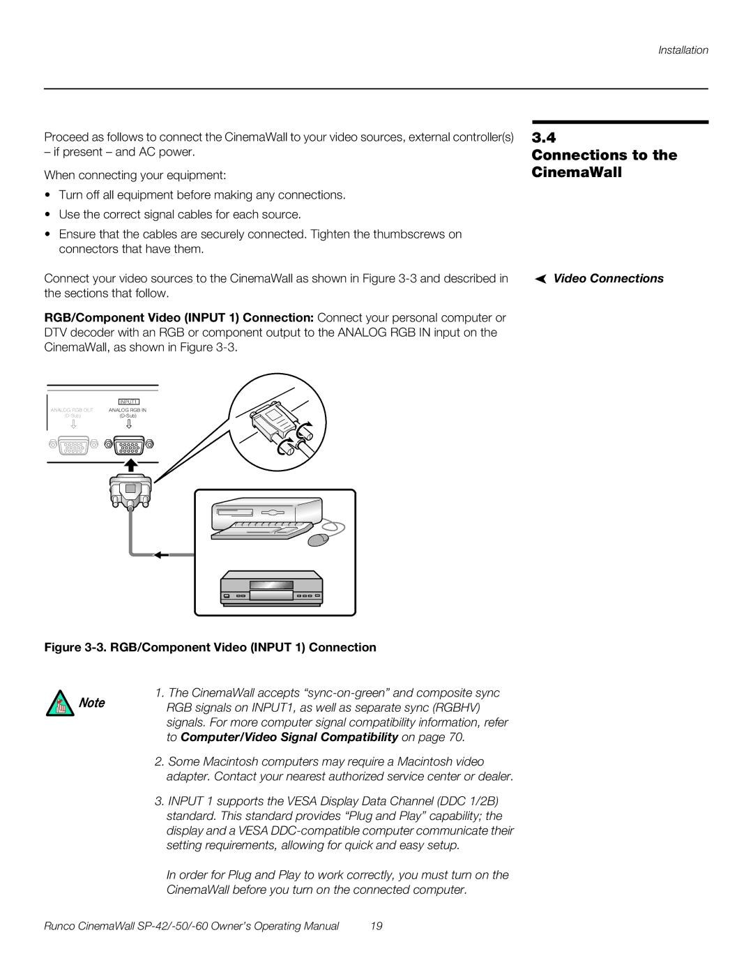
Connect your video sources to the CinemaWall as shown in Figure
RGB/Component Video (INPUT 1) Connection: Connect your personal computer or DTV decoder with an RGB or component output to the ANALOG RGB IN input on the CinemaWall, as shown in Figure
3.4
Connections to the CinemaWall
Video Connections
|
|
|
|
|
|
|
| INPUT1 |
| ||
ANALOG RGB OUT | ANALOG RGB IN | ||||
| |||||
|
|
|
|
|
|
|
|
|
|
|
|
|
|
|
|
|
|
|
|
|
|
|
|
Figure 3-3. RGB/Component Video (INPUT 1) Connection
1. The CinemaWall accepts
Note RGB signals on INPUT1, as well as separate sync (RGBHV) signals. For more computer signal compatibility information, refer to Computer/Video Signal Compatibility on page 70.
2.Some Macintosh computers may require a Macintosh video adapter. Contact your nearest authorized service center or dealer.
3.INPUT 1 supports the VESA Display Data Channel (DDC 1/2B) standard. This standard provides “Plug and Play” capability; the display and a VESA
In order for Plug and Play to work correctly, you must turn on the
CinemaWall before you turn on the connected computer.
Runco CinemaWall | 19 |