1 - INSTALLATION AND COMMISSIONING
Description of power supply ports
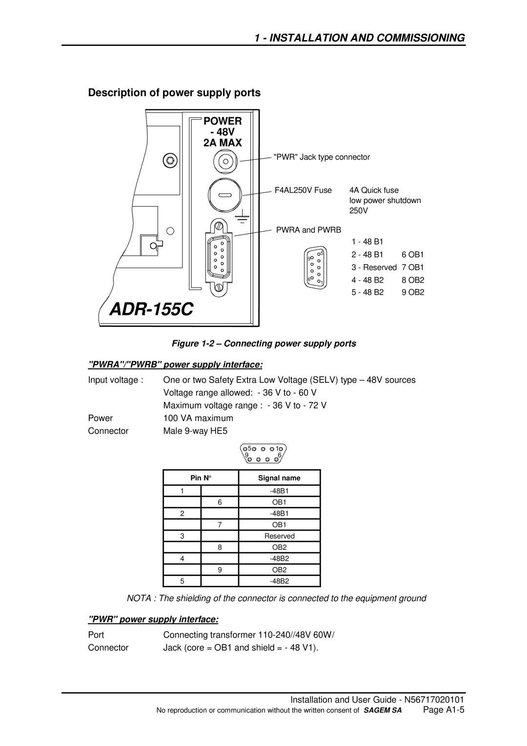
POWER |
- 48V |
2A MAX |
|
"PWR" Jack type connector | |
F4AL250V Fuse | 4A Quick fuse |
| low power shutdown |
| 250V |
PWRA and PWRB |
|
|
| |
| 1 | - 48 B1 |
| |
5 | 2 | - 48 B1 | 6 OB1 | |
9 | ||||
|
|
| ||
| 3 | - Reserved | 7 OB1 | |
6 | 4 | - 48 B2 | 8 OB2 | |
1 | ||||
| 5 | - 48 B2 | 9 OB2 |
| Figure | ||||||||
"PWRA"/"PWRB" power supply interface: | |||||||||
Input voltage : | One or two Safety Extra Low Voltage (SELV) type – 48V sources | ||||||||
| Voltage range allowed: - 36 V to - 60 V | ||||||||
| Maximum voltage range : - 36 V to - 72 V | ||||||||
Power | 100 VA maximum |
|
|
|
| ||||
Connector | Male |
|
|
|
| ||||
|
|
|
|
|
|
|
|
|
|
| 5 | 1 |
|
| |||||
| 9 |
| 6 |
|
| ||||
|
|
|
|
|
|
|
| ||
|
|
|
|
| |||||
| Pin N° |
| Signal name |
| |||||
|
|
|
|
|
|
|
| ||
| 1 |
|
|
|
|
| |||
|
| 6 |
|
|
| OB1 |
| ||
| 2 |
|
|
|
|
| |||
|
| 7 |
|
|
| OB1 |
| ||
| 3 |
|
|
|
| Reserved |
| ||
|
| 8 |
|
|
| OB2 |
| ||
| 4 |
|
|
|
|
| |||
|
| 9 |
|
|
| OB2 |
| ||
| 5 |
|
|
|
|
| |||
NOTA : The shielding of the connector is connected to the equipment ground | |||||||||
"PWR" power supply interface: |
|
|
|
| |||||
Port | Connecting transformer | ||||||||
Connector | Jack (core = OB1 and shield = - 48 V1). | ||||||||
Installation and User Guide - N56717020101
No reproduction or communication without the written consent of SAGEM SA | Page |