1 - INSTALLATION AND COMMISSIONING
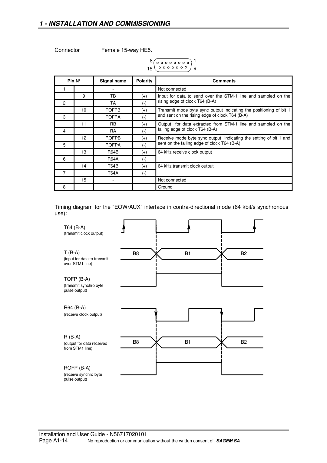
Connector | Female |
| ||
|
|
| 8 | 1 |
|
|
| 15 | 9 |
|
|
|
|
|
Pin N° | Signal name | Polarity | Comments | |
|
|
|
|
|
1 |
| - |
| Not connected |
|
|
|
|
|
| 9 | TB | (+) | Input for data to send over the |
|
|
|
| rising edge of clock T64 |
2 |
| TA | ||
|
| |||
|
|
|
|
|
| 10 | TOFPB | (+) | Transmit mode byte sync output indicating the positioning of bit 1 |
|
|
|
| and sent on the rising edge of clock T64 |
3 |
| TOFPA | ||
|
| |||
| 11 | RB | (+) | Output for data extracted from |
4 |
| RA | falling edge of clock T64 | |
|
| |||
| 12 | ROFPB | (+) | Receive mode byte sync output indicating the setting of bit 1 and |
5 |
| ROFPA | sent on the falling edge of clock T64 | |
|
| |||
| 13 | R64B | (+) | 64 kHz receive clock output |
6 |
| R64A |
| |
| 14 | T64B | (+) | 64 kHz transmit clock output |
7 |
| T64A |
| |
| 15 | - |
| Not connected |
8 |
|
|
| Ground |
Timing diagram for the "EOW/AUX" interface in
T64
(transmit clock output)
T
(input for data to transmit over STM1 line)
TOFP (B-A)
(transmit synchro byte pulse output)
R64
(receive clock output)
R
(output for data received from STM1 line)
ROFP
(receive synchro byte pulse output)
| B8 |
|
| B1 |
|
| B2 | ||
|
|
|
| ||||||
|
|
|
| ||||||
|
|
|
|
|
|
|
|
|
|
|
|
|
|
|
|
|
|
|
|
|
|
|
|
|
|
|
|
|
|
|
|
|
|
|
|
|
|
|
|
|
|
|
|
|
|
|
|
|
|
|
|
|
|
|
|
|
|
|
|
|
|
|
|
|
|
|
|
|
|
|
|
|
|
|
|
|
|
|
|
|
|
|
|
|
|
|
|
|
|
|
|
|
|
|
|
|
|
|
|
|
|
|
|
|
|
|
|
|
|
|
|
|
|
|
|
|
|
|
|
|
|
|
|
|
|
|
|
|
|
|
|
|
|
|
|
|
|
|
|
|
|
|
|
|
|
|
|
|
|
|
|
|
|
|
|
|
|
|
|
|
|
|
|
|
|
|
|
|
|
|
|
|
|
|
|
|
|
|
|
|
|
|
|
|
|
|
|
|
|
|
|
|
|
|
|
|
|
|
|
|
|
|
|
|
|
|
|
|
|
|
|
|
|
|
|
|
|
|
|
|
|
|
|
|
|
|
|
|
|
B8 |
|
| B1 |
|
| B2 |
|
|
|
| |||
|
|
|
| |||
|
|
|
|
|
|
|
|
|
|
|
|
|
|
|
|
|
|
|
|
|
|
|
|
|
|
|
|
|
|
|
|
|
|
|
|
|
|
|
|
|
|
|
|
|
|
|
|
|
|
|
|
|
|
|
|
|
|
|
|
|
|
|
Installation and User Guide - N56717020101
Page | No reproduction or communication without the written consent of SAGEM SA |