1 - INSTALLATION AND COMMISSIONING
"MNGT" Interface: |
|
|
|
|
|
| ||
Port | V.11 synchronous (differential) interconnection possible with other SAGEM | |||||||
|
| equipment ADR155C, FOT 155C, through serial synchronous links used in | ||||||
|
| codirectional mode at 64 kbit/s or master | ||||||
|
| defined by the ADR 155C) |
|
|
| |||
Bit rate | 64 kbit/s, |
|
|
|
|
|
| |
Connector | Female |
|
|
|
|
| ||
|
|
|
|
|
|
|
|
|
|
|
|
| 5 | 1 |
| ||
|
|
|
| 9 |
| 6 |
| |
|
|
|
|
|
|
|
|
|
|
|
|
|
|
|
|
|
|
Pin N° | Signal name | Polarity |
|
|
|
| Comments | |
|
|
|
|
| ||||
1 |
| GND |
| Ground (no connected) | ||||
|
|
|
|
| ||||
| 6 | RXPB | (+) | Input for data received over the P interface and sampled on the | ||||
|
|
|
| rising edge of receive clock RXCLKP | ||||
2 |
| RXPA | ||||||
|
|
|
|
|
| |||
|
|
|
|
| ||||
| 7 | TXPB | (+) | Output for data sent over the P interface on the falling edge of | ||||
|
|
|
| transmit clock TXCLKP | ||||
3 |
| TXPA | ||||||
|
|
|
|
|
| |||
| 8 | TXCLKPB | (+) | Output for transmit clock; in codirectional mode, the transmit clock | ||||
|
|
|
| timing is derived from the equipment's internal timing | ||||
4 |
| TXCLKPA | ||||||
|
|
|
|
|
| |||
| 9 | RXCLKPB | (+) | Receive clock input | ||||
5 |
| RXCLKPA |
|
|
|
|
| |
*In slave contradirectional mode (coming) TXCLK signals are inputs.
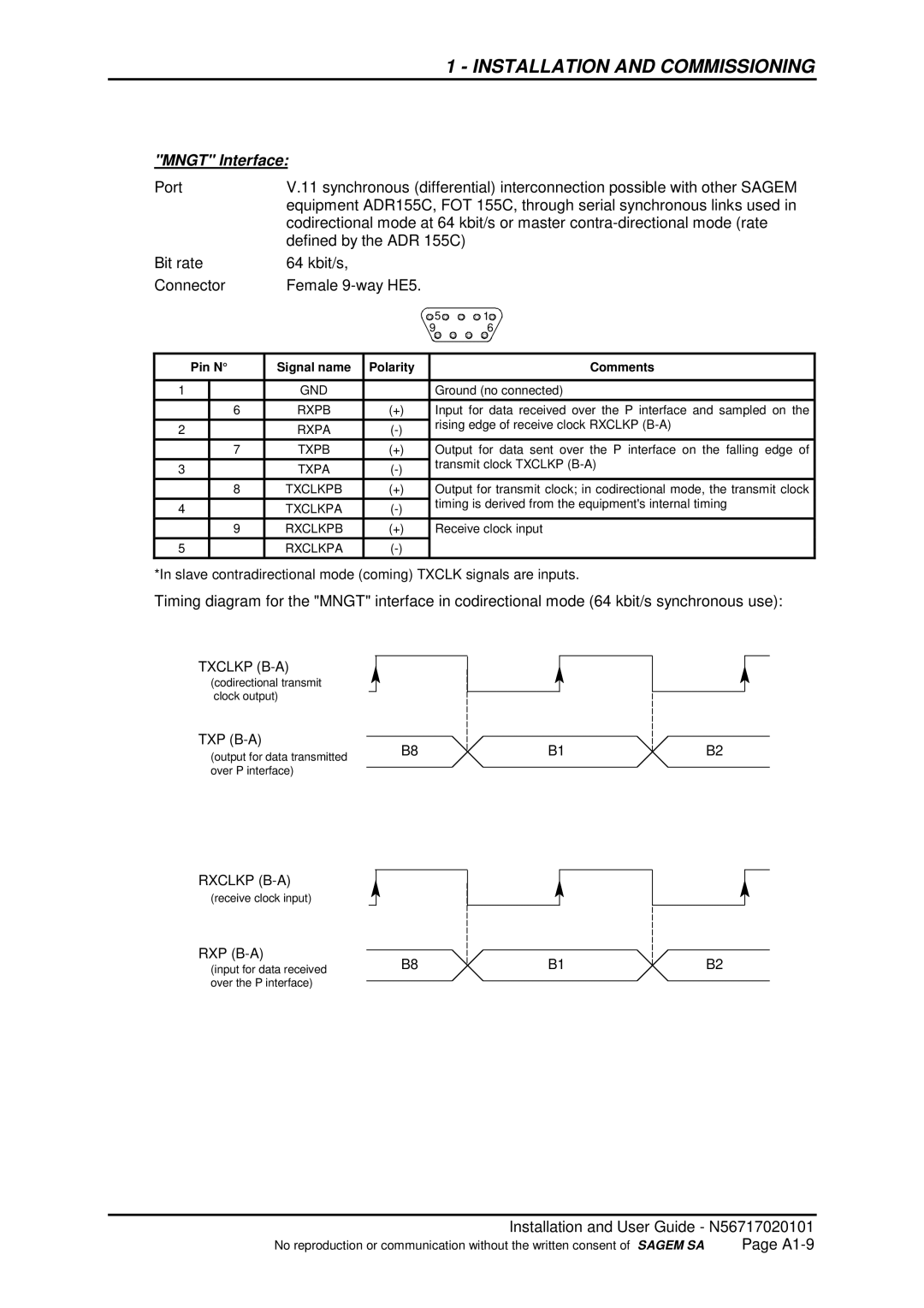
Timing diagram for the "MNGT" interface in codirectional mode (64 kbit/s synchronous use):
TXCLKP
(codirectional transmit clock output)
TXP
(output for data transmitted | B8 |
| |
over P interface) |
|
|
RXCLKP
(receive clock input)
RXP
(input for data received | B8 |
| |
over the P interface) |
|
|
B1
B1
B2
B2
Installation and User Guide - N56717020101
No reproduction or communication without the written consent of SAGEM SA | Page |
