1 - INSTALLATION AND COMMISSIONING
This screen is also used to:
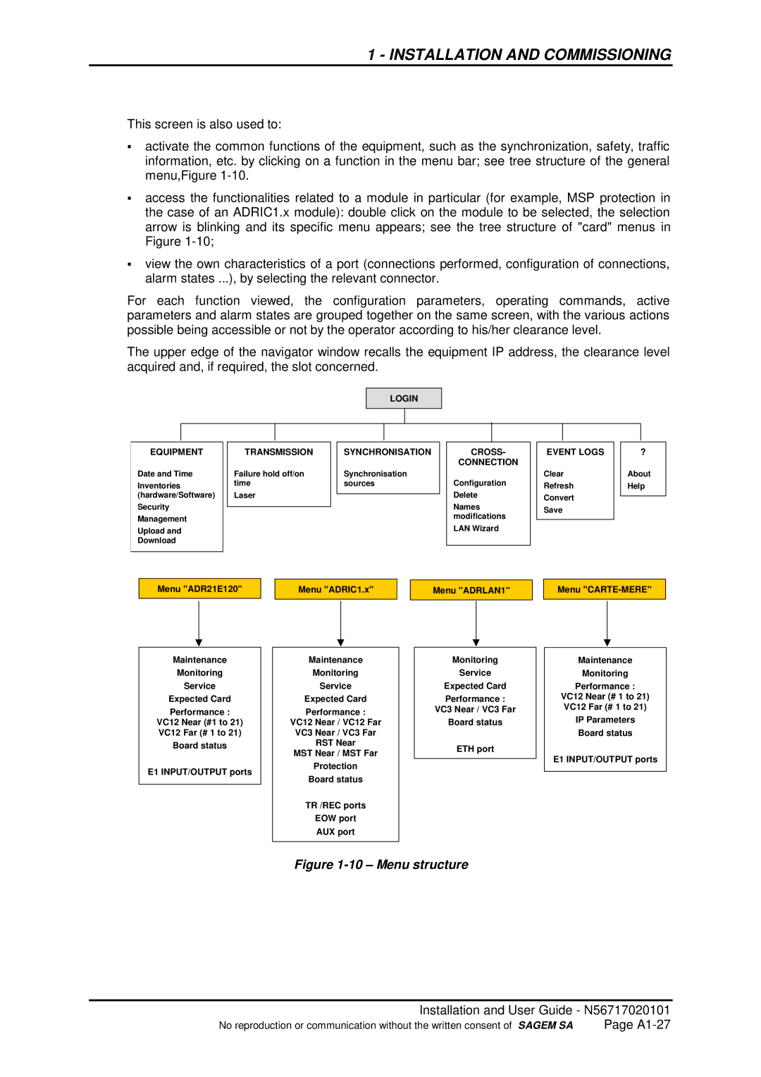
activate the common functions of the equipment, such as the synchronization, safety, traffic information, etc. by clicking on a function in the menu bar; see tree structure of the general
Smenu,Figure
access the functionalities related to a module in particular (for example, MSP protection in the case of an ADRIC1.x module): double click on the module to be selected, the selection arrow is blinking and its specific menu appears; see the tree structure of "card" menus in
SFigure
view the own characteristics of a port (connections performed, configuration of connections, alarm states ...), by selecting the relevant connector.
For each function viewed, the configuration parameters, operating commands, active parameters and alarm states are grouped together on the same screen, with the various actions possible being accessible or not by the operator according to his/her clearance level.
The upper edge of the navigator window recalls the equipment IP address, the clearance level acquired and, if required, the slot concerned.
LOGIN
EQUIPMENT
Date and Time
Inventories (hardware/Software)
Security
Management
Upload and
Download
TRANSMISSION
Failure hold off/on time
Laser
SYNCHRONISATION
Synchronisation sources
CROSS-
CONNECTION
Configuration
Delete
Names modifications
LAN Wizard
EVENT LOGS
Clear
Refresh
Convert
Save
?
About
Help
Menu "ADR21E120"
Maintenance
Monitoring
Service
Expected Card
Performance :
VC12 Near (#1 to 21) VC12 Far (# 1 to 21)
Board status
E1 INPUT/OUTPUT ports
Menu "ADRIC1.x"
Maintenance
Monitoring
Service
Expected Card
Performance :
VC12 Near / VC12 Far
VC3 Near / VC3 Far
RST Near
MST Near / MST Far
Protection
Board status
TR /REC ports
EOW port
AUX port
Menu "ADRLAN1"
Monitoring
Service
Expected Card
Performance :
VC3 Near / VC3 Far
Board status
ETH port
Menu
Maintenance
Monitoring
Performance :
VC12 Near (# 1 to 21) VC12 Far (# 1 to 21)
IP Parameters
Board status
E1 INPUT/OUTPUT ports
Figure 1-10 – Menu structure
Installation and User Guide - N56717020101
No reproduction or communication without the written consent of SAGEM SA | Page |