4. Service procedures
5Motor capacitor ............ Both in indoor and outdoor unit
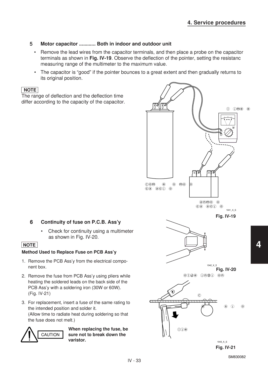
•Remove the lead wires from the capacitor terminals, and then place a probe on the capacitor terminals as shown in Fig.
•The capacitor is “good” if the pointer bounces to a great extent and then gradually returns to its original position.
NOTE
The range of deflection and the deflection time differ according to the capacity of the capacitor.
Multimeter
Ω
Compressor motor capacitor
Fan motor capacitor
1041_X_S
6Continuity of fuse on P.C.B. Ass’y
•Check for continuity using a multimeter as shown in Fig. IV-20.
NOTE
Method Used to Replace Fuse on PCB Ass’y
1.Remove the PCB Ass’y from the electrical compo- nent box.
2.Remove the fuse from PCB Ass’y using pliers while heating the soldered leads on the back side of the PCB Ass’y with a soldering iron (30W or 60W). (Fig.
3.For replacement, insert a fuse of the same rating to the intended position and solder it.
(Allow time to radiate heat during soldering so that the fuse does not melt.)
Fig.
![]() Fuse
Fuse
1042_X_S
Fig.
Soldering iron
PCB Ass’y
![]() Fuse Varistor
Fuse Varistor
4
| When replacing the fuse, be | Pliers |
CAUTION | sure not to break down the |
|
| varistor. | 1043_X_S |
| ||
|
| |
|
| Fig. |
SM830082
IV - 33