2. Processes and functions
2-2 Cold Draft Prevention (Heating Cycle)
2 |
The cold draft prevention function controls indoor fan speed so a strong draft of cold air will not blow out before the indoor heat exchange coils have warmed up.
❑STANDBY shows on the remote controller when the indoor fan speed is LL (very low) or OFF. This condition occurs in the following 3 cases:
•During Thermo OFF (refer to
•During the defrosting operation (refer to
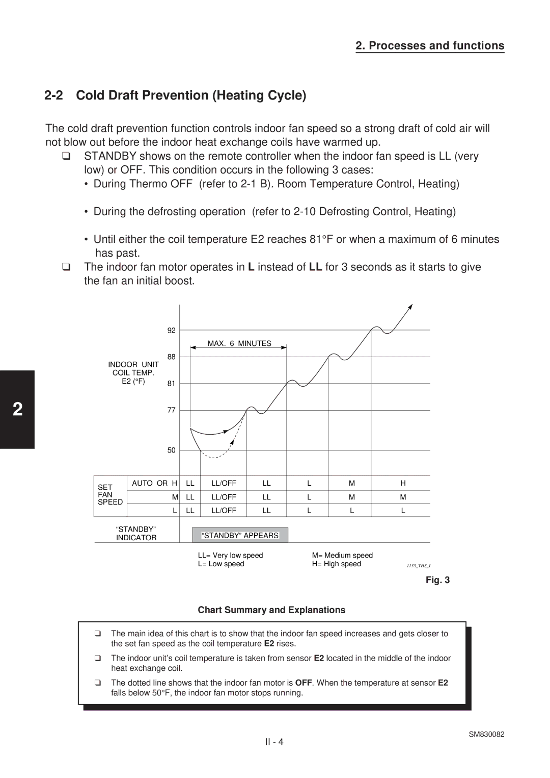
•Until either the coil temperature E2 reaches 81°F or when a maximum of 6 minutes has past.
❑The indoor fan motor operates in L instead of LL for 3 seconds as it starts to give the fan an initial boost.
|
|
| 92 |
|
|
|
|
|
|
|
|
|
|
|
|
|
|
|
|
|
| MAX. 6 MINUTES |
|
|
|
|
| ||
INDOOR UNIT | 88 |
|
|
|
|
|
|
|
|
| ||||
|
|
|
|
|
|
|
|
|
|
| ||||
|
|
|
|
|
|
|
|
|
|
| ||||
|
|
|
|
|
|
|
|
|
|
|
| |||
| COIL TEMP. |
|
|
|
|
|
|
|
|
|
|
|
| |
| E2 (°F) | 81 |
|
|
|
|
|
|
|
|
|
|
| |
|
|
|
|
|
|
|
|
|
|
|
|
|
| |
|
|
| 77 |
|
|
|
|
|
|
|
|
|
|
|
|
|
|
|
|
|
|
|
|
|
|
|
|
| |
|
|
| 50 |
|
|
|
|
|
|
|
|
|
|
|
|
|
|
|
|
|
|
|
|
|
|
|
|
| |
|
|
|
|
|
|
|
|
|
|
|
|
|
| |
|
|
|
|
|
|
|
|
|
|
|
|
|
| |
SET |
| AUTO OR H | LL |
| LL/OFF | LL | L |
| M |
| H | |||
|
|
|
|
|
|
|
|
|
|
|
|
|
| |
FAN |
|
| M | LL |
| LL/OFF | LL | L |
| M |
| M | ||
SPEED |
|
|
|
| ||||||||||
|
|
|
|
|
|
|
|
|
|
|
|
| ||
| L | LL |
| LL/OFF | LL | L |
| L |
| L | ||||
|
|
|
|
|
| |||||||||
|
|
|
|
|
|
|
|
|
|
|
|
|
|
|
| “STANDBY” |
|
|
|
|
|
|
|
|
|
|
|
| |
|
|
|
|
|
| “STANDBY” APPEARS |
|
|
|
|
| |||
| INDICATOR |
|
|
|
|
|
|
|
|
|
| |||
|
|
|
|
|
|
|
|
|
|
|
|
| ||
|
|
|
|
|
|
| LL= Very low speed |
| M= Medium speed |
| ||||
|
|
|
|
|
|
| L= Low speed |
|
| H= High speed | 1135_THS_I | |||
Fig. 3
Chart Summary and Explanations
❑The main idea of this chart is to show that the indoor fan speed increases and gets closer to the set fan speed as the coil temperature E2 rises.
❑The indoor unit’s coil temperature is taken from sensor E2 located in the middle of the indoor heat exchange coil.
❑The dotted line shows that the indoor fan motor is OFF. When the temperature at sensor E2 falls below 50°F, the indoor fan motor stops running.
SM830082
II - 4