Backup Battery
The system employs one or more 6.5 AH (Model 1265) or 7.0 AH (Model 1270) sealed
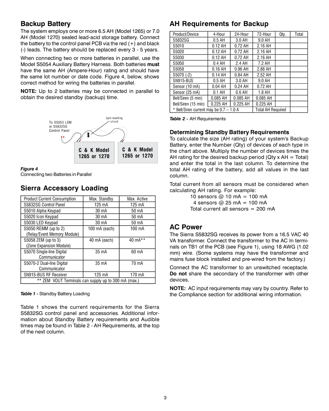
When connecting two or more batteries in parallel, use the Model S5054 Auxiliary Battery Harness. Both batteries must have the same AH
NOTE: Up to 2 batteries may be connected in parallel to obtain the desired standby (backup) time.
| |
To S5053 LSM | circuit |
| |
or S5832SG |
|
Control Panel |
|
AH Requirements for Backup
Product/Device | Qty. | Total | ||||
S5832SG | 0.5 | AH | 3.0 AH | 9.0 AH |
|
|
S5010 | 0.12 AH | 0.72 AH | 2.16 AH |
|
| |
S5020 | 0.12 AH | 0.72 AH | 2.16 AH |
|
| |
S5030 | 0.12 AH | 0.72 AH | 2.16 AH |
|
| |
S5050 | 0.4 | AH | 2.4 AH | 7.2 AH |
|
|
S5058 | 0.16 AH | 0.96 AH | 2.88 AH |
|
| |
S5070 | 0.14 AH | 0.84 AH | 2.52 AH |
|
| |
| 0.5 | AH | 3.0 AH | 9.0 AH |
|
|
Sensor (10 mA) | 0.04 AH | 0.24 AH | 0.72 AH |
|
| |
Sensor (25 mA) | 0.1 | AH | 0.6 AH | 1.8 AH |
|
|
Bell/Siren (5 min) | 0.085 AH | 0.085 AH | 0.085 AH |
|
| |
Bell/Siren (15 min) | 0.225 AH | 0.225 AH | 0.225 AH |
|
| |
* Bell/Siren current may be | 0.7 – 1.0 A | Total AH Required |
| |||
Table 2 - AH Requirements
Determining Standby Battery Requirements
C & K Model 1265 or 1270
Figure 4
Connecting two Batteries in Parallel
Sierra Accessory Loading
C & K Model 1265 or 1270
To calculate the size (AH rating) of your system's Backup Battery, enter the Number (Qty) of devices of each type in the chart above. Multiply the number of devices times the AH rating for the desired backup period (Qty x AH = Total) and enter the total in the last column. To determine the total AH rating of the battery, add all values in the last column.
Total current from all sensors must be considered when calculating AH rating. For example:
Product Current Consumption | Max. Standby | Max. Active | |
S5832SG Control Panel | 125 mA | 125 mA | |
S5010 | Alpha Keypad | 30 mA | 50 mA |
S5020 | Icon Keypad | 30 mA | 50 mA |
S5030 LED Keypad | 30 mA | 50 mA | |
S5050 | REMM (up to 2) | 100 mA (each) | 100 mA |
(Relay/Event Memory Module) |
|
| |
S5058 | ZEM (up to 3) | 40 mA (each) | 40 mA** |
(Zone Expansion Module) |
|
| |
S5070 | 35 mA | 60 mA | |
| Communicator |
|
|
35 mA | 70 mA | ||
| Communicator |
|
|
125 mA | 170 mA | ||
| ** ZEM VOUT Terminals can supply up to 300 mA (max.) | ||
Table 1 - Standby Battery Loading |
| ||
Table 1 shows the current requirements for the Sierra S5832SG control panel and accessories. Additional infor- mation about Standby Battery requirements and Audible times may be found in Table 2 - AH Requirements, at the top of the next column.
10 sensors @ 10 mA = 100 mA
4 sensors @ 25 mA = 100 mA Total current all sensors = 200 mA
AC Power
The Sierra S5832SG receives its power from a 16.5 VAC 40 VA transformer. Connect the transformer to the AC In termi- nals on TB1 of the PCB (see Figure 1), using 18 AWG (1.02
mm)wire. (Some systems may have the transformer and mains fuse block installed and
Connect the AC transformer to an unswitched receptacle. Do not share the secondary of the transformer with other devices.
NOTE: AC input requirements may vary by country. Refer to the Compliance section for additional wiring information.
3