Power Management
The
The above numbers assume that the only active connections are the 802.11 wireless interface and the serial interface (for example, there are no connections to the GPIOs). Power consumption specifications are subject to change; contact Silex for more information.
Serial Ports
Standard serial
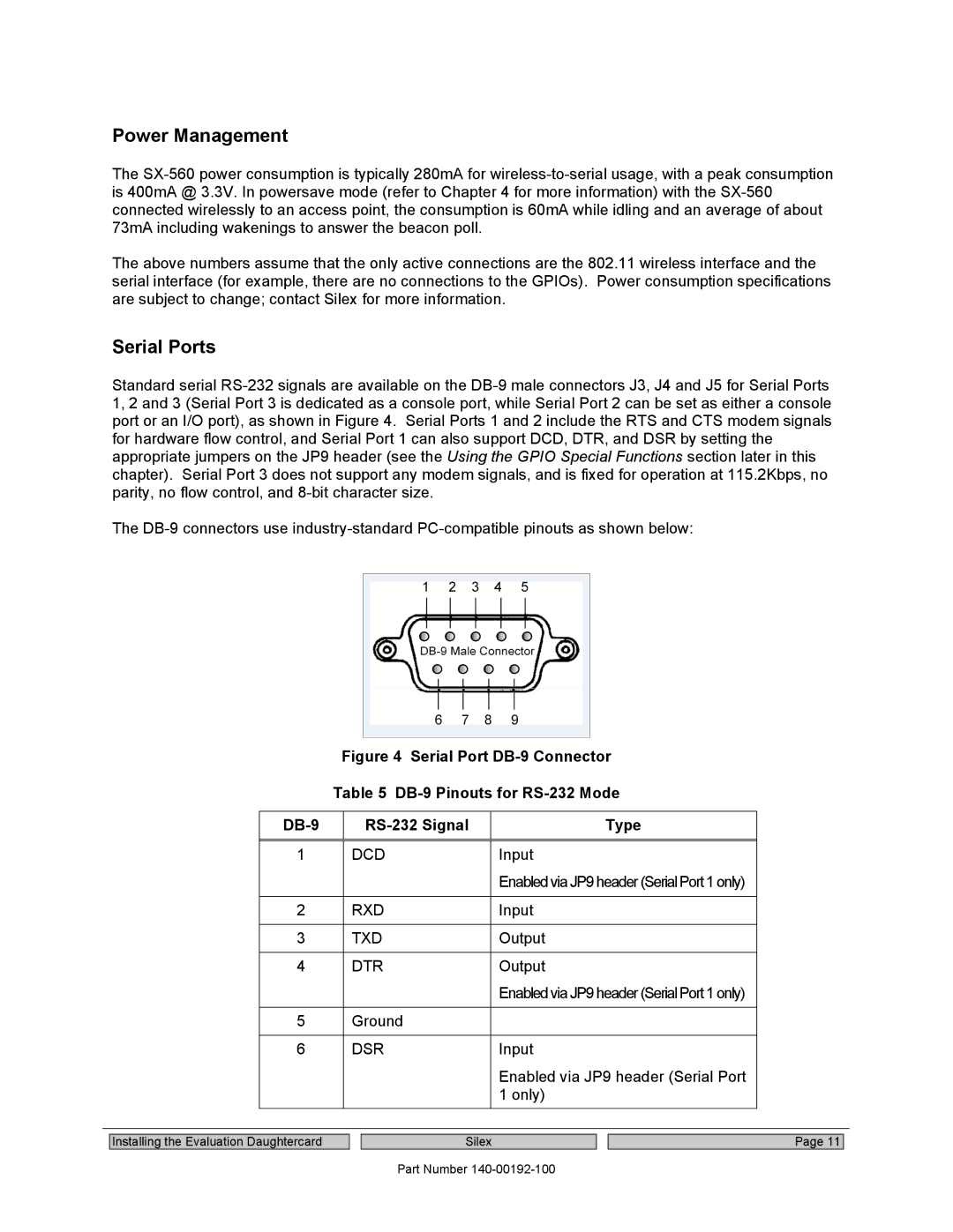
The
Figure 4 Serial Port DB-9 Connector
Table 5 DB-9 Pinouts for RS-232 Mode
| Type | |
|
|
|
1 | DCD | Input |
|
| EnabledviaJP9header(SerialPort1only) |
|
|
|
2 | RXD | Input |
|
|
|
3 | TXD | Output |
|
|
|
4 | DTR | Output |
|
| EnabledviaJP9header(SerialPort1only) |
|
|
|
5 | Ground |
|
|
|
|
6 | DSR | Input |
|
| Enabled via JP9 header (Serial Port |
|
| 1 only) |
|
|
|
Installing the Evaluation Daughtercard
Silex
Part Number
Page 11
