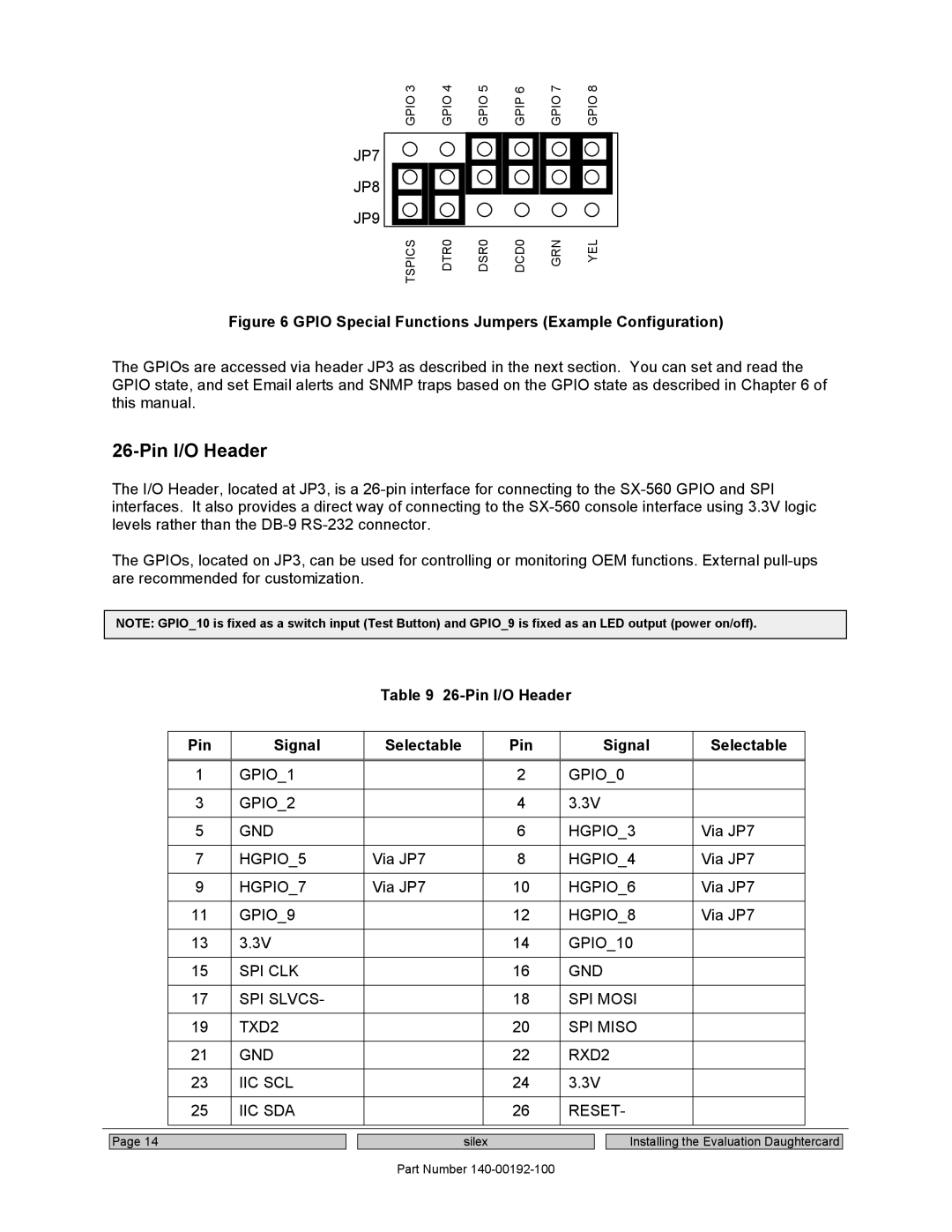
GPIO 3 | GPIO 4 | GPIO 5 | GPIP 6 | GPIO 7 | GPIO 8 |
JP7
JP8
JP9
TSPICS | DTR0 | DSR0 | DCD0 | GRN | YEL |
Figure 6 GPIO Special Functions Jumpers (Example Configuration)
The GPIOs are accessed via header JP3 as described in the next section. You can set and read the GPIO state, and set Email alerts and SNMP traps based on the GPIO state as described in Chapter 6 of this manual.
26-Pin I/O Header
The I/O Header, located at JP3, is a
The GPIOs, located on JP3, can be used for controlling or monitoring OEM functions. External
NOTE: GPIO_10 is fixed as a switch input (Test Button) and GPIO_9 is fixed as an LED output (power on/off).
Table 9 26-Pin I/O Header
| Pin | Signal | Selectable | Pin | Signal | Selectable |
|
|
|
|
|
|
|
|
|
| 1 | GPIO_1 |
| 2 | GPIO_0 |
|
|
|
|
|
|
|
|
|
|
| 3 | GPIO_2 |
| 4 | 3.3V |
|
|
|
|
|
|
|
|
|
|
| 5 | GND |
| 6 | HGPIO_3 | Via JP7 |
|
|
|
|
|
|
|
|
|
| 7 | HGPIO_5 | Via JP7 | 8 | HGPIO_4 | Via JP7 |
|
|
|
|
|
|
|
|
|
| 9 | HGPIO_7 | Via JP7 | 10 | HGPIO_6 | Via JP7 |
|
|
|
|
|
|
|
|
|
| 11 | GPIO_9 |
| 12 | HGPIO_8 | Via JP7 |
|
|
|
|
|
|
|
|
|
| 13 | 3.3V |
| 14 | GPIO_10 |
|
|
|
|
|
|
|
|
|
|
| 15 | SPI CLK |
| 16 | GND |
|
|
|
|
|
|
|
|
|
|
| 17 | SPI SLVCS- |
| 18 | SPI MOSI |
|
|
|
|
|
|
|
|
|
|
| 19 | TXD2 |
| 20 | SPI MISO |
|
|
|
|
|
|
|
|
|
|
| 21 | GND |
| 22 | RXD2 |
|
|
|
|
|
|
|
|
|
|
| 23 | IIC SCL |
| 24 | 3.3V |
|
|
|
|
|
|
|
|
|
|
| 25 | IIC SDA |
| 26 | RESET- |
|
|
|
|
|
|
|
|
|
|
|
|
|
|
|
|
|
|
Page 14
silex
Part Number
Installing the Evaluation Daughtercard