As discussed in the previous section, GPIOs 3 through 8 are set by default for special functions such as modem controls. To use GPIOs 3 through 8 as normal GPIOs, you must place a jumper between JP7 and JP8 for the specific GPIO as described in the previous section. GPIO 2 can also have a special function if SPI mode is selected for the LCD display via header JP12 as described in the LCD Interface section later in this chapter.
Table 10 General Purpose I/O Signal Descriptions
Silex | S3C2412 | I/O | Special Function |
GPIO_0 | GPF 0 | O |
|
GPIO_1 | GPF 1 | O |
|
GPIO_2 | GPF 2 | O | Special function SPI_CS- for LCD display |
GPIO_3 | GPF 3 | O | Special function TEMP_CS SPI temperature sensor enable |
GPIO_4 | GPF 4 | O | Special function, nDTR0 |
GPIO_5 | GPF 5 | I | Special function, nDSR0 |
GPIO_6 | GPF 6 | I | Special function, nDCD0 |
GPIO_7 | GPF 7 | O | Special function, nLED_3; wired link |
GPIO_8 | GPG 5 | O | Special function, nLED_2; wireless link |
GPIO_9 | GPG 6 | O | nLED_1; power on/status* |
|
|
|
|
GPIO_10 | GPG 7 | I | Switch Input; 1 = off, 0 = switch depressed* |
|
|
|
|
*The functionality of GPIO_9 and GPIO_10 cannot be changed by the user.
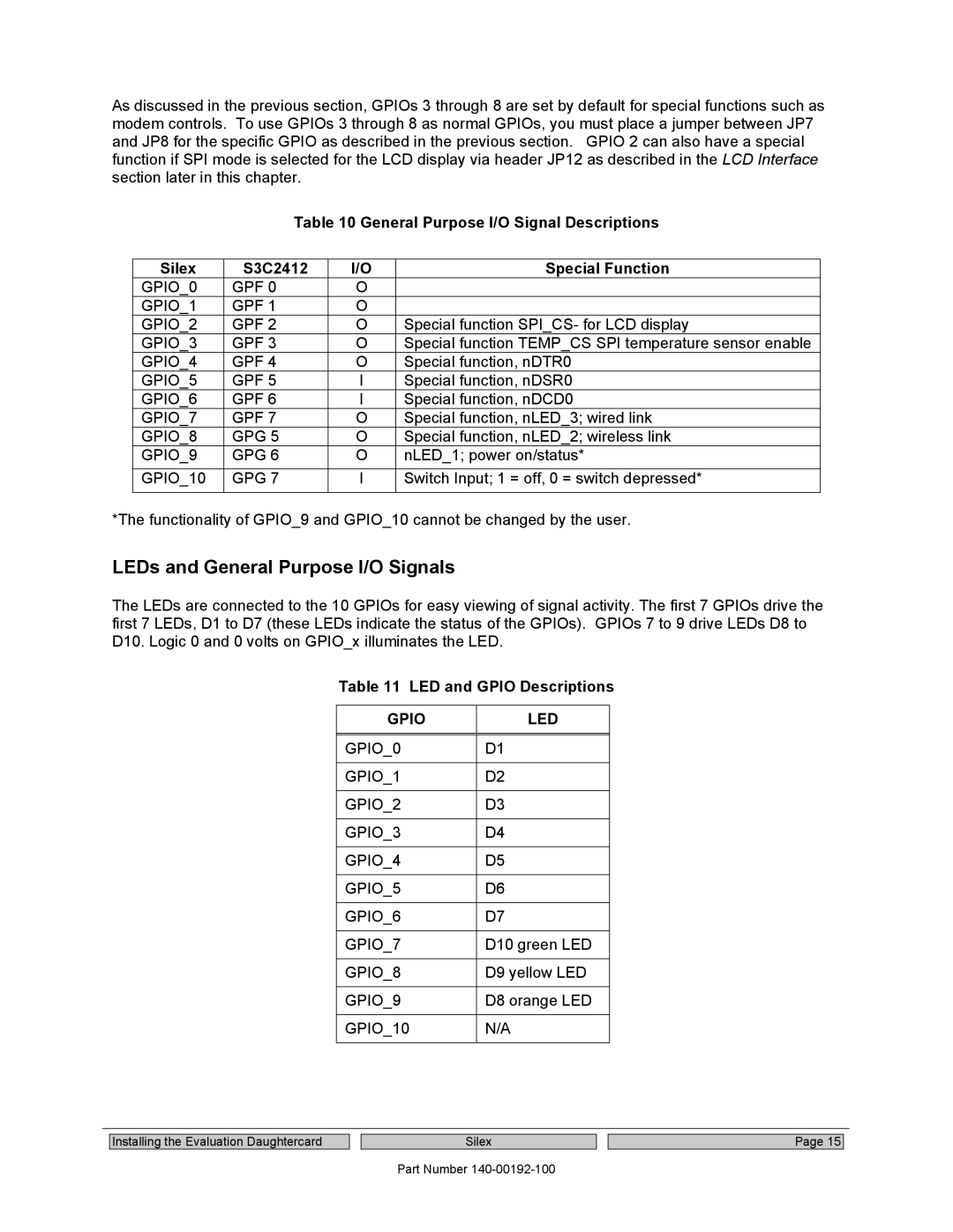
LEDs and General Purpose I/O Signals
The LEDs are connected to the 10 GPIOs for easy viewing of signal activity. The first 7 GPIOs drive the first 7 LEDs, D1 to D7 (these LEDs indicate the status of the GPIOs). GPIOs 7 to 9 drive LEDs D8 to D10. Logic 0 and 0 volts on GPIO_x illuminates the LED.
Table 11 LED and GPIO Descriptions
GPIO | LED |
|
|
GPIO_0 | D1 |
|
|
GPIO_1 | D2 |
|
|
GPIO_2 | D3 |
|
|
GPIO_3 | D4 |
|
|
GPIO_4 | D5 |
|
|
GPIO_5 | D6 |
|
|
GPIO_6 | D7 |
|
|
GPIO_7 | D10 green LED |
|
|
GPIO_8 | D9 yellow LED |
|
|
GPIO_9 | D8 orange LED |
|
|
GPIO_10 | N/A |
|
|
Installing the Evaluation Daughtercard
Silex
Part Number
Page 15