|
| Type |
|
|
|
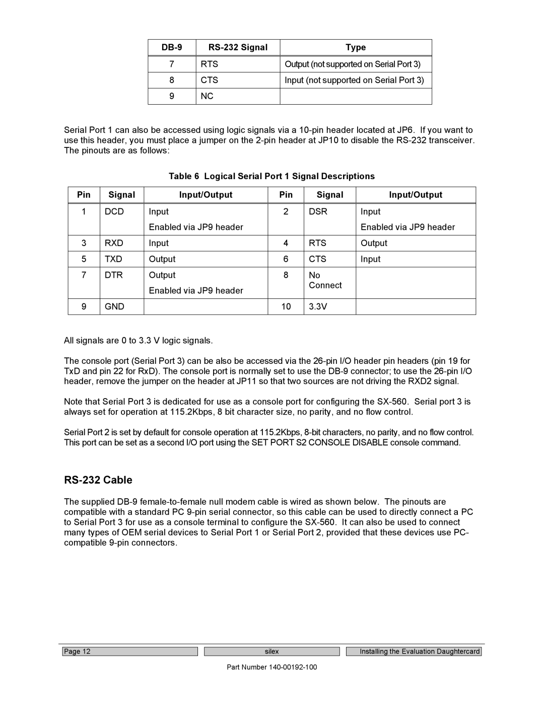
7 | RTS | Output (not supported on Serial Port 3) |
|
|
|
8 | CTS | Input (not supported on Serial Port 3) |
|
|
|
9 | NC |
|
|
|
|
Serial Port 1 can also be accessed using logic signals via a
Table 6 Logical Serial Port 1 Signal Descriptions
Pin | Signal | Input/Output | Pin | Signal | Input/Output |
|
|
|
|
|
|
1 | DCD | Input | 2 | DSR | Input |
|
| Enabled via JP9 header |
|
| Enabled via JP9 header |
|
|
|
|
|
|
3 | RXD | Input | 4 | RTS | Output |
|
|
|
|
|
|
5 | TXD | Output | 6 | CTS | Input |
|
|
|
|
|
|
7 | DTR | Output | 8 | No |
|
|
| Enabled via JP9 header |
| Connect |
|
|
|
|
|
| |
|
|
|
|
|
|
9 | GND |
| 10 | 3.3V |
|
|
|
|
|
|
|
All signals are 0 to 3.3 V logic signals.
The console port (Serial Port 3) can be also be accessed via the
Note that Serial Port 3 is dedicated for use as a console port for configuring the
Serial Port 2 is set by default for console operation at 115.2Kbps,
RS-232 Cable
The supplied
Page 12
silex
Part Number
Installing the Evaluation Daughtercard