TMS320DM355 specifications
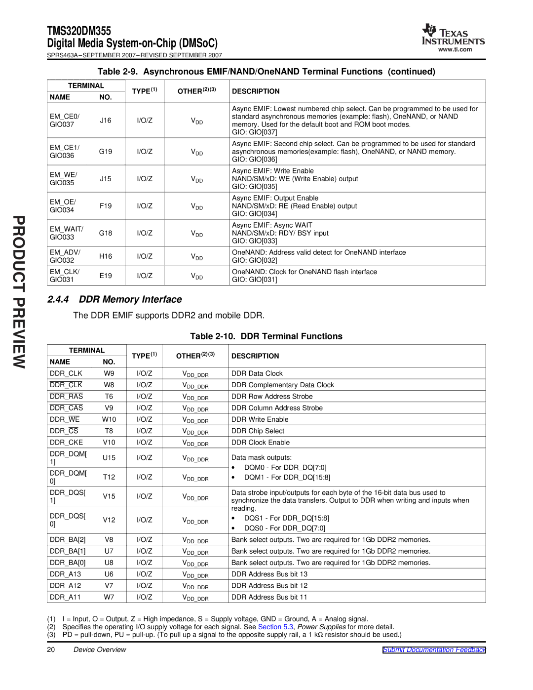
The Texas Instruments TMS320DM355 is a versatile digital signal processor designed to support a wide array of multimedia applications, specifically in the realms of digital video and audio processing. As part of the TMS320 family of digital signal processors, the DM355 brings a blend of computational power, energy efficiency, and integrated features that make it highly effective for tasks such as video encoding, decoding, and general signal processing.One of the standout features of the DM355 is its advanced DaVinci architecture, which is specifically optimized for multimedia tasks. This architecture integrates both DSP and application processing functionalities. The dual-core architecture includes a high-performance DSP core that specializes in real-time signal processing alongside an ARM926EJ-S RISC microprocessor, facilitating the execution of complex algorithms and control tasks.
The DM355 offers robust multimedia processing capabilities with support for several video formats, including MPEG-2, MPEG-4, H.264, and JPEG. This enables developers to create powerful video applications for a variety of devices, from industrial systems to consumer electronics. Its processing capabilities extend to audio processing, allowing it to efficiently handle audio codecs and enhance audio quality in applications ranging from IP cameras to set-top boxes.
In terms of connectivity, the TMS320DM355 supports various interfaces including USB 2.0, Ethernet, and various serial interfaces like UART, SPI, and I2C. This wide range of connectivity options ensures that the DM355 can easily interface with different peripherals and network components, making it a suitable choice for networked applications.
Energy efficiency is another significant advantage of the DM355. With a focus on low power consumption, the device is designed to operate effectively in battery-powered and heat-sensitive environments. Its low thermal design power allows for extended operational life and reduced thermal management requirements, making it ideal for portable devices.
Furthermore, the DM355 is supported by a comprehensive software development framework, including the TI Code Composer Studio and a range of middleware tools, which streamline application development and speed up time to market. Its rich ecosystem enhances its usability across different applications, ensuring that developers can leverage the full potential of the hardware.
In summary, the Texas Instruments TMS320DM355 stands out as a powerful yet cost-effective DSP solution, combining advanced multimedia processing capabilities, robust connectivity options, and energy efficiency. Its unique architecture and extensive support resources make it a preferred choice for developers seeking to create innovative multimedia solutions.

