Peripheral Architecture |
|
| |
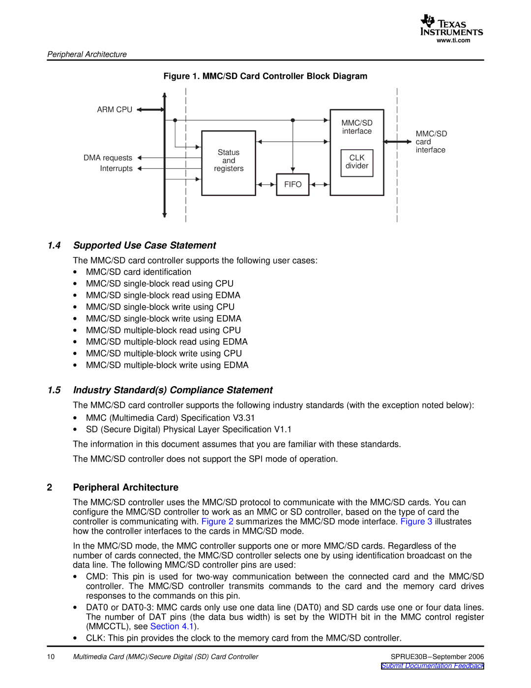
| Figure 1. MMC/SD Card Controller Block Diagram | ||
ARM CPU |
|
| |
|
| MMC/SD | |
|
| interface | |
DMA requests | Status | CLK | |
and | |||
| divider | ||
Interrupts | registers | ||
| |||
|
| FIFO | |
1.4Supported Use Case Statement
The MMC/SD card controller supports the following user cases:
∙MMC/SD card identification
∙MMC/SD
∙MMC/SD
∙MMC/SD
∙MMC/SD
∙MMC/SD
∙MMC/SD
∙MMC/SD
∙MMC/SD
www.ti.com
MMC/SD card interface
1.5Industry Standard(s) Compliance Statement
The MMC/SD card controller supports the following industry standards (with the exception noted below):
∙MMC (Multimedia Card) Specification V3.31
∙SD (Secure Digital) Physical Layer Specification V1.1
The information in this document assumes that you are familiar with these standards.
The MMC/SD controller does not support the SPI mode of operation.
2Peripheral Architecture
The MMC/SD controller uses the MMC/SD protocol to communicate with the MMC/SD cards. You can configure the MMC/SD controller to work as an MMC or SD controller, based on the type of card the controller is communicating with. Figure 2 summarizes the MMC/SD mode interface. Figure 3 illustrates how the controller interfaces to the cards in MMC/SD mode.
In the MMC/SD mode, the MMC controller supports one or more MMC/SD cards. Regardless of the number of cards connected, the MMC/SD controller selects one by using identification broadcast on the data line. The following MMC/SD controller pins are used:
∙CMD: This pin is used for
∙DAT0 or
∙CLK: This pin provides the clock to the memory card from the MMC/SD controller.
10 | Multimedia Card (MMC)/Secure Digital (SD) Card Controller | SPRUE30B |