www.ti.com
Registers
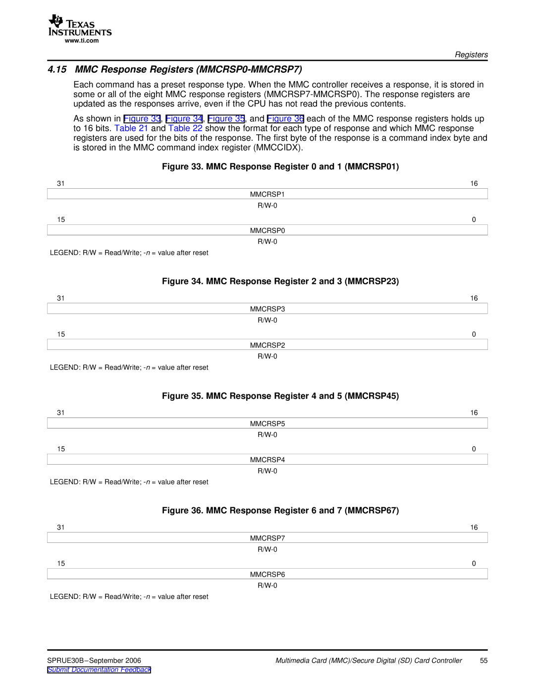
4.15 MMC Response Registers (MMCRSP0-MMCRSP7)
Each command has a preset response type. When the MMC controller receives a response, it is stored in some or all of the eight MMC response registers
As shown in Figure 33, Figure 34, Figure 35, and Figure 36 each of the MMC response registers holds up to 16 bits. Table 21 and Table 22 show the format for each type of response and which MMC response registers are used for the bits of the response. The first byte of the response is a command index byte and is stored in the MMC command index register (MMCCIDX).
| Figure 33. MMC Response Register 0 and 1 (MMCRSP01) |
31 | 16 |
| MMCRSP1 |
| |
15 | 0 |
MMCRSP0
LEGEND: R/W = Read/Write;
| Figure 34. MMC Response Register 2 and 3 (MMCRSP23) |
31 | 16 |
| MMCRSP3 |
| |
15 | 0 |
MMCRSP2
LEGEND: R/W = Read/Write;
| Figure 35. MMC Response Register 4 and 5 (MMCRSP45) |
31 | 16 |
| MMCRSP5 |
| |
15 | 0 |
MMCRSP4
LEGEND: R/W = Read/Write;
| Figure 36. MMC Response Register 6 and 7 (MMCRSP67) |
31 | 16 |
| MMCRSP7 |
| |
15 | 0 |
| MMCRSP6 |
LEGEND: R/W = Read/Write;
SPRUE30B | Multimedia Card (MMC)/Secure Digital (SD) Card Controller | 55 |
Submit Documentation Feedback |
|
|