www.ti.com
Procedures for Common Operations
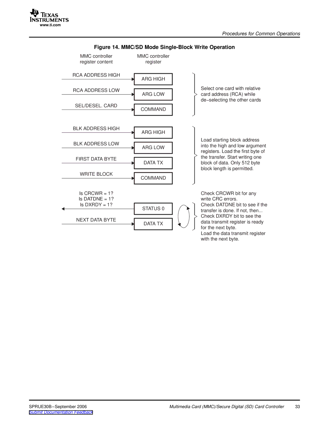
Figure 14. MMC/SD Mode Single-Block Write Operation
MMC controller register content
RCA ADDRESS HIGH
RCA ADDRESS LOW
SEL/DESEL. CARD
BLK ADDRESS HIGH
BLK ADDRESS LOW
FIRST DATA BYTE
WRITE BLOCK
Is CRCWR = 1?
Is DATDNE = 1?
Is DXRDY = 1?
NEXT DATA BYTE
MMC controller
register
ARG HIGH
ARG LOW
COMMAND
ARG HIGH
ARG LOW
DATA TX
COMMAND
STATUS 0
DATA TX
Select one card with relative card address (RCA) while de−selecting the other cards
Load starting block address into the high and low argument registers. Load the first byte of the transfer. Start writing one block of data. Only 512 byte block length is permitted.
Check CRCWR bit for any write CRC errors.
Check DATDNE bit to see if the transfer is done. If not, then...
Check DXRDY bit to see the data transmit register is ready for the next byte.
Load the data transmit register with the next byte.
SPRUE30B | Multimedia Card (MMC)/Secure Digital (SD) Card Controller | 33 |