www.ti.com
Registers
Table 10. MMC Interrupt Mask Register (MMCIM) Field Descriptions (continued)
Bit | Field | Value | Description |
3 | ETOUTRD |
| |
|
| 0 | |
|
| 1 | |
2 | ERSPDNE |
| Command/response done (RSPDNE) interrupt enable. |
|
| 0 | Command/response done interrupt is disabled. |
|
| 1 | Command/response done interrupt is enabled. |
1 | EBSYDNE |
| Busy done (BSYDNE) interrupt enable. |
|
| 0 | Busy done interrupt is disabled. |
|
| 1 | Busy done interrupt is enabled. |
0 | EDATDNE |
| Data done (DATDNE) interrupt enable. |
|
| 0 | Data done interrupt is disabled. |
|
| 1 | Data done interrupt is enabled. |
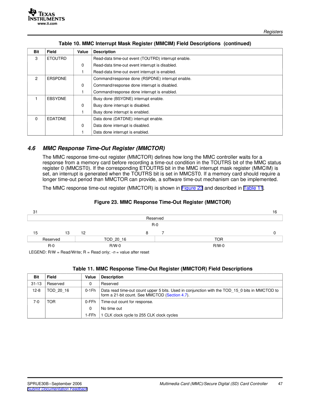
4.6MMC Response Time-Out Register (MMCTOR)
The MMC response
The MMC response
Figure 23. MMC Response Time-Out Register (MMCTOR)
31 |
|
|
|
| 16 |
|
|
| Reserved |
| |
|
|
|
|
| |
15 | 13 | 12 | 8 | 7 | 0 |
| Reserved |
| TOD_20_16 |
| TOR |
|
|
| |||
LEGEND: R/W = Read/Write; R = Read only;
Table 11. MMC Response Time-Out Register (MMCTOR) Field Descriptions
Bit | Field | Value | Description |
Reserved | 0 | Reserved | |
TOD_20_16 | Data read | ||
|
|
| form a |
TOR | |||
|
| 0 | No time out |
|
| 1 CLK clock cycle to 255 CLK clock cycles |
SPRUE30B | Multimedia Card (MMC)/Secure Digital (SD) Card Controller | 47 |
Submit Documentation Feedback |
|
|